42
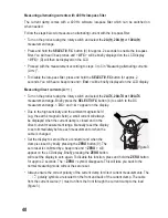
• Turn on the device using the rotary switch and select the measurement range
V
.
• Press and hold the
SELECT/V.F.C
button (4) for approx. 2 seconds to enable the low-pass
filter. You will hear 3 beep tones and <
UFC
> will be briefly displayed on the LCD display.
<
VFC
> (D) will then be displayed on the LCD.
• Proceed with the measurement according to steps 2 to 5 in "Measuring "AC" voltages
(V )".
•
To disable the low-pass filter, press and hold the
SELECT/V.F.C
button for approx. 2
seconds. You will hear a beep tone and <
End
> will be briefly displayed on the LCD display.
Measuring "DC" voltages (V )
• Turn on the device and select the measurement range
V .
Briefly press the
SELECT/V.F.C
button (4) to switch to the DC measurement range. <
DC
> and <
mV
>
appear on the display.
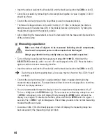
• Insert the red test lead into the
V
socket (8) and the black test lead into the
COM
socket (7).
• Connect both of the test prods to the measured object (battery, circuit etc.). The red test
prod corresponds to the positive terminal; the black test prod corresponds to the negative
terminal.
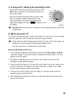
• The current measured value is displayed together with the respective polarity on the display.
A minus "-" symbol before the measured value indicates that the measured voltage is
negative (or the test leads have been reversed).
The "V DC/AC" voltage range has an input resistance of ≥10 MOhm.
• After completing the measurement, remove the current clamp from the measured object and
turn off the device.
d) Measuring resistance
Make sure that all objects to be measured including circuit components,
circuits and component parts are disconnected and discharged.
• Turn on the device and select the measurement range
Ω
.
• Insert the red test lead into the
V
socket (8) and the black test lead into the
COM
socket (7).
• Check the test leads by connecting the two test probes together. A resistance value of
approx 0 - 1.5 Ohms should be shown (inherent resistance of the test leads).

