background image

1.Safety Information

3

Measurement Limits

The protection circuitry of the multimeter can prevent damage to the instrument and

protect against the danger of electric shock, when the Measurement Limits are not

exceeded. To ensure safe operation of the instrument, do not exceed the Measurement

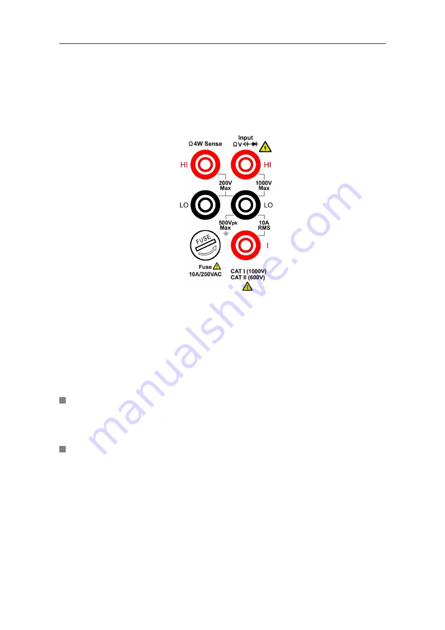
Limits shown on the front panel, it is defined as follows:

The user-replaceable 10 A current-protection fuse is on the front panel. To maintain

protection, replace fuse only with fuse of the specified type and rating. About the

specified type and rating of the fuse, please refer to "7 Current Terminal Fuse" in "Front

Panel Overview" on page 6.

Main Input Terminals (HI Input and LO Input) Measurement Limits

The HI and LO input terminals are used for voltage, resistance, continuity, frequency

(period), capacitance, diode, and temperature test measurements. Two Measurement

Limits are defined for these terminals:

HI Input to LO Input Measurement Limit

The Measurement Limit from HI Input to LO Input is 1000 VDC or 750 VAC, which is

also the maximum voltage measurement. This limit can also be expressed as 1000

Vpk maximum.

LO Input to Ground Measurement Limit

The LO input terminal can safely "float" a maximum of 500 Vpk relative to ground,

where ground is defined as the Protective Earth Conductor in the AC mains power

cord connected to the instrument.

As implied by the above limits, the Measurement Limit for the HI input terminal is a

maximum of 1500 Vpk relative to ground when LO Input is at its maximum of 500 Vpk

relative to ground.

Current Input Terminal (I) Measurement Limits

The Measurement Limit from the current input terminal (I) to the LO Input terminal is 10

A (DC or AC). Note that the current input terminals will always be at approximately the

same voltage as the LO Input terminal, unless a current protection fuse is open.

Summary of Contents for VC-7055BT

Page 1: ...i VC 7055BT Digital Multimeter User Manual...

Page 2: ...verview 6 Rear Panel Overview 8 User Interface 8 Power On 9 Measurement Connections 10 3 Functions and Operations 12 To Set The Range 12 Measurement Speed 13 Basic Measurement Functions 13 Measuring D...

Page 3: ...C Voltage 30 True RMS AC Measurements 31 Loading Errors AC Voltage 32 Crest Factor Errors non sinusoidal inputs 33 5 Troubleshooting 34 6 Technical Specifications 35 7 Appendix 37 Appendix A Enclosure...

Page 4: ...e instrument or other property might occur Safety Symbols Symbols on the Product The following symbol may appear on the product Direct current DC Warning risk of electric shock Alternating current AC...

Page 5: ...s product Refer to the user s manual for the Measurement Limits before connecting to the instrument Do not exceed any of the Measurement Limits defined in the following section Do not operate without...

Page 6: ...mperature test measurements Two Measurement Limits are defined for these terminals HI Input to LO Input Measurement Limit The Measurement Limit from HI Input to LO Input is 1000 VDC or 750 VAC which i...

Page 7: ...ins power up to 600 VAC under Category II overvoltage conditions Measurement category definition Measurement CAT I applies to measurements performed on circuits not directly connected to the AC mains...

Page 8: ...Manual You can check whether there is any loss of accessories with reference to this description If it is found that there is any accessory lost or damaged please get in touch with our distributor res...

Page 9: ...Item Name Description 1 LCD Display the user interface 2 Menu selection Keys Activate the corresponding menu 3 Operation Keys Save Collect data in manual record The instrument saves current reading e...

Page 10: ...a parameter press to move the cursor press to increase or decrease the value 7 Current Terminal Fuse The rating is 10 A 250 VAC To replace the fuse Turn off the multimeter and remove the power cord U...

Page 11: ...ough this port 2 Line Fuse The fuse rating is 250 V F1AL To replace the fuse see page 38 Appendix C Line Fuse Replacement 3 AC Mains Input AC mains input connector 4 Chassis Ground Screw To ground the...

Page 12: ...to the AC supply using the supplied power cord Warning To avoid electric shock the instrument must be grounded properly 2 Press down the power button at the front panel the screen shows the boot scree...

Page 13: ...t to the multimeter according to the method below To avoid instrument damage do not discretionarily switch the measurement function when measuring DC Voltage Measurement AC Voltage Measurement DC Curr...

Page 14: ...2 Quick Start 11 Capacitance Measurement Frequency Period Measurement Temperature Measurement...

Page 15: ...own on the right menu you can press the key to switch between auto and manual range Press to enable manual range and increase or decrease the measurement range 2nd Method Select the range in the measu...

Page 16: ...ments Operating Steps 1 Enable the DCV measurement Press on the front panel to enter DCV measurement mode 2 Connect the test lead 3 Set the range Press the Range softkey to set the range Auto range au...

Page 17: ...Set the range Press the Range softkey to set the range Auto range automatically selects the range for the measurement based on the input Note 750 V input protection is available in all ranges 10 over...

Page 18: ...front panel and the built in 12 A current input fuse 10 over range for all ranges except 10 A range If the reading exceeds 10 5 A in 10 A range overload will be displayed 4 Set the measurement speed P...

Page 19: ...e page 13 Measurement Speed 5 Set the relative value Press the Rel softkey to turn on or off the relative operation For relative operation the multimeter subtracts the pre specified value of REL opera...

Page 20: ...he Model softkey to switch between 2W and 4W 2 wire Resistance 4 wire Resistance 2 Connect the test lead 3 Set the range Press the Range softkey to set the range Auto range automatically selects the r...

Page 21: ...stance is small relative operation is recommended in order to reduce the error caused by test lead Both ends of the measured resistance should be placed far away from your hands and desks that can con...

Page 22: ...ys measured resistance without beeping 1000 Displays Open with no beep Diode Test This section describes how to configure diode test Operating Steps 1 Enable the diode test Press on the front panel pr...

Page 23: ...ly selects the range for the measurement based on the input Note 1000 V input protection is available in all ranges 10 over range for all ranges except 50000 F range If the reading exceeds 50500 F in...

Page 24: ...Period measurement 2 Connect the test lead 3 Note Frequency range 20 Hz to 60 MHz 750 V input protection is available in all ranges 4 Set the relative value Press the Rel softkey to turn on or off the...

Page 25: ...Temp Val only the temperature value will be displayed Meas Val only the measurement value will be displayed All both the temperature value on the main display and the measurement value will be display...

Page 26: ...he primary measurement functions and their associated secondary measurements are gray back color indicates valid combinations Primary measurement function DCV DCI ACV ACI FREQ PERIOD 2WR 4WR CAP Secon...

Page 27: ...panel key press the Max Min softkey press the Static softkey to select ON Remarks Press the Clear Readings softkey to clear reading memory and restart statistics dB dBm The dB and dBm scaling functio...

Page 28: ...t the reference resistance The value may be 50 default 75 93 110 124 125 135 150 250 300 500 600 800 900 1000 1200 or 8000 Press the dB Ref Value softkey to select the relative value The relative valu...

Page 29: ...ng manual record Save only the main display readings 2 View the manual record Press the front panel key press the Manual record softkey to display the data table Press keys to turn the page When the d...

Page 30: ...ble shows the readings taken press keys to turn the page Note Automatic recording function supports switching measurement function In auto range the relay switch may cause jitter the data at this time...

Page 31: ...the parameters of the system related functions in utility menu Press the panel key to view the instrument model firmware version serial number and checksum Language This model only supports English Ba...

Page 32: ...tility BLight 100 Math dB dBm Off On Off Function dB Rel R 50 Db Rel 0 Max Min Static Off Record Auto Clear Manual Clear Point 100 Interval 1S Aoto On Off Off Other Run Stop Run Rel Off Beeper Off Thr...

Page 33: ...ur when the resistance of the DUT Device Under Test is an appreciable percentage of the multimeter s input resistance as shown below Vs ideal DUT voltage Rs DUT source resistance Ri multimeter input r...

Page 34: ...ts of the input waveform are measured DC is rejected As seen in the figure above for sine waves triangle waves and square waves the AC coupled and AC DC values are equal because these waveforms do not...

Page 35: ...also adds capacitance and loading The table below shows the multimeter s approximate input resistance at various frequencies Input Frequency Input Resistance 100 Hz 1 M 1 kHz 850 k 10 kHz 160 k 100 k...

Page 36: ...actor errors do not apply for input signals below 100Hz You can estimate the measurement error due to signal crest factor as shown below Total Error Error Sine wave Error Crest factor Error Bandwidth...

Page 37: ...ignal is input 1 Check whether the test lead is correctly inserted into the current input terminals I terminal and LO Input terminal 2 Check whether the current terminal fuse at the front panel is bur...

Page 38: ...mA 0 001 mA 0 15 20 500 mA 0 01 mA 0 15 10 5 A 0 0001 A 0 5 10 10 A 5 0 001 A 0 5 10 True RMS AC Current 6 500 uA 500 mA 0 5 20 5 A 10 A 1 5 20 Resistance 7 500 0 01 0 1 10 5 k 0 0001 k 0 1 5 50 k 0...

Page 39: ...out relative operation add 0 20 additional error in 2 wire ohms function 8 Except for special marks when frequency 10M Hz the specification is applicable to 1V AC input voltage when frequency 10 MHz t...

Page 40: ...ent electrical shock disconnect the instrument from AC mains power and disconnect all test leads before cleaning 2 Clean the outside of the instrument using a wet soft cloth not dripping water Do not...

Page 41: ...ltages that could result in personal injury or death Use only the correct fuse type Failure to do so could result in personal injury or instrument damage Voltage Fuse 90 240 V AC 250 V F1AL To perform...

Reviews: