44
b) Incorrect wiring alarm
The DMM automatically detects which terminals are connected
to the test leads. If the test leads are connected to the wrong
terminals (which can be dangerous for the user and damage the
DMM), the DMM triggers an acoustic and optical alarm.
If you switch to another measurement mode (except current
mode) when the test leads are connected to the terminals, the
DMM triggers an alarm. The alarm is also triggered when the
measuring input is switched from the 10 A terminal to the mAµA
terminal.
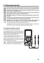
If the alarm is triggered and “LEAd” appears on the display, check
that the leads are connected to the correct terminals and that you
have selected the correct measurement mode.
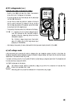
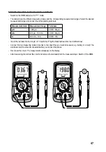
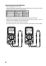
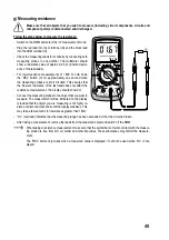
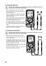
The diagram shows an example of incorrectly connected leads
that need to be reconnected.
The multimeter triggers the alarm when the terminals are con-
nected as follows:
Measurement mode
V/Ω/
/
mA/µA/
10 A
Connected terminals
mA/µA/
/10 A 10 A
mA/µA/
If the alarm is triggered, check that you have selected the correct measurement mode and that the cables
are connected to the correct terminals. The correct terminals are indicated on the display for each meas-
urement range.
c) AC voltage mode (“V
”)
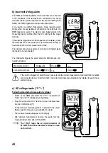
Follow the steps below to measure AC voltages:
- Switch on the DMM and select the “V
” measurement
mode. “AC” and “V” will appear on the display.
- Plug the red lead into the V terminal (G) and the black lead
into the COM terminal (H).
- Connect the two measuring probes in parallel to the object
that you want to measure (e.g. generator or circuit).
- The measured value will appear on the display.
- After taking a measurement, remove the leads from the
measured object and switch off the DMM.
The “V/AC” range has an input resistance of
≥10 MΩ. This means that there is almost no load
on the circuit.

