47
7. Product description
The multimeter (DMM) displays measurements on a digital display. The multimeter has 6000 counts (count = smallest
display value). The true RMS value is used when measuring voltages and currents. The correct socket assignment is
displayed according to the measurement mode selected. Incorrect socket assignment is indicated by a warning sound
and warning indicator. This increases the operational safety of the multimeter for the user.
If the DMM is not operated for approx. 15 minutes, the device switches off automatically. This saves battery power and
extends the period of operation. The automatic shut-off feature can be disabled manually.
The DMM can be used to take measurements up to CAT III 600 V. It is suitable for use in hobby and professional
applications.
Protective caps may be attached to the angled test lead plugs. Remove these before inserting the test leads into the
multimeter.
The DMM can be placed on a level surface using the fold-out stand for better readability.
With this multimeter, it is no longer necessary to replace a fuse that has accidentally tripped in the mA/µA measure-
ment range. The built-in PTC protection elements limit current flow in the event of an overload and thus protect the
multimeter and the current circuit. The PTC protection elements reset themselves after tripping and a short cool-down
period. For this, the current measurement circuit must only be interrupted briefly.
The battery and fuse compartment can only be opened when all test leads have been removed from the multimeter.
When the battery and fuse compartment are open, the test leads cannot be inserted into the measurement sockets.
This is a built-in safety feature designed to protect the user.
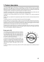
Rotary control (D)
The individual measurement modes are selected via a rotary con-
trol. The automatic range selection “Auto” is active. This means
that the appropriate measurement range is set automatically. The
current measurement ranges must be set manually. Always start
current measurements with the largest measurement range, and
then switch to a smaller range if necessary.
The rotary control has a mode button (I). With the “SELECT” but-
ton, switch to a sub-mode if the measurement mode is double
assigned (e.g. switching resistance measuring for diode test and
continuity test or AC/DC switching). The sub-modes are marked
in grey. Press the “SELECT” button again to switch to the next
sub-mode.
To switch the multimeter off, move the rotary control to the “OFF” position. Always switch the multimeter off when it
is not in use.

