background image

58

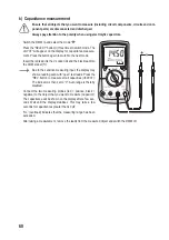
h) Resistance measurement 

  Ensure that all objects that you want to measure (including circuit components, circuits and com-

ponent parts) are disconnected and discharged. 

Proceed as follows to measure the resistance:
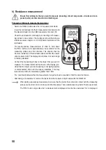
-  Switch the DMM on and select the “Ω” measurement mode. 
-   Insert the red test lead into the Ω measurement socket (G) and 

the black test lead into the COM measurement socket (H).

-   Check the test leads for continuity by connecting both measur-

ing probes to one another. The multimeter should then show a 

resistance value of approx 0 - 0.5 Ω (inherent resistance of the 

test leads). 

-   For  low-impedance  measurements  of  <600  Ω,  hold  down 

the “REL” button (C) for approximately one second when the 

measuring probes are short circuited. This ensures that the 

inherent resistance of the test leads does not affect the resist-

ance measurement. The display should show 0 Ω. Auto range 

is thereby disabled.

-   Connect the measuring probes to the object that you want to 

measure. The measurement will be shown on the display (pro-

vided that the object you are measuring is not highly resistive 

or disconnected). Wait until the display stabilises. This may 

take a few seconds for resistances greater than 1 MΩ.

-   “OL” (overload) indicates that the measurement range has been exceeded or that the circuit is broken.
-  After taking a measurement, remove the leads from the measured object and switch the DMM off.

  When taking a resistance measurement, ensure that the points that come into contact with the measuring 

probes are free from dirt, oil, solder and other impurities. These substances may distort the measurement.


The “REL” button only works when a measurement is displayed. It cannot be used when “OL” is displayed.

Summary of Contents for VC276 TRMS

Page 1: ...647182 Seite 2 38 Operating Instructions Digital Multimeter VC276 TRMS Item No 1647182 Page 39 75 Mode d emploi Multim tre num rique VC276 TRMS N de commande 1647182 Page 76 112 Gebruiksaanwijzing Dig...

Page 2: ...sung V 15 d LoZ Spannungsmessung 16 e Strommessung A 17 f Frequenzmessung 20 g Messung der Pulsdauer in 20 h Widerstandsmessung 21 i Diodentest 22 j Durchgangspr fung 22 k Kapazit tsmessung 23 l Tempe...

Page 3: ...e als professioneller Anwender auch schwierigen Aufgaben gerecht Voltcraft bietet Ihnen zuverl ssige Technologie zu einem au ergew hnlich g nstigen Preis Leistungs Verh ltnis Wir sind uns sicher Ihr S...

Page 4: ...Messungen an elektrischen und elektronischen Ger ten welche ber einen Netzste cker direkt mit Netzspannung versorgt werden Diese Kategorie umfasst auch alle kleineren Kategorien z B CAT I zur Messung...

Page 5: ...selbstr cksetzenden PTC Sicherungen ausgestattet Bei berlast wir der Stromfluss begrenzt und das Messger t gesch tzt Dadurch entf llt in dieser Messfunktion der l stige Sicherungswechsel Eine Niedrig...

Page 6: ...kt darf nicht ge ndert bzw umgebaut werden Lesen Sie die Bedienungsanleitung sorgf ltig durch und bewahren Sie diese f r sp teres Nachschlagen auf Die Sicherheitshinweise sind unbedingt zu beachten 4...

Page 7: ...e Unfallverh tungsvorschriften des Verbandes der gewerblichen Berufsgenossenschaften f r elektrische Anlagen und Betriebsmittel zu beachten In Schulen und Ausbildungseinrichtungen Hobby und Selbsthilf...

Page 8: ...netischen Feldern Sendeantennen oder HF Generatoren Dadurch kann der Messwert verf lscht werden Wenn anzunehmen ist dass ein gefahrloser Betrieb nicht mehr m glich ist so ist das Ger t au er Be trieb...

Page 9: ...se Bezugspotential Minus I SELECT Taste zur Funktionsumschaltung J Low Imp 400 k Taste zur Impedanzumschaltung K NCV Sensorfl che Stirnseite L Sockel mit Schiebeabdeckung f r optionale Befestigungsgur...

Page 10: ...ng zu ersetzen Die eingebauten PTC Schutzelemente begrenzen bei einer berlastung den Stromfluss und sch tzen so das Messger t und den Stromkreis Die PTC Schutzelemente stellen sich nach einer Ausl sun...

Page 11: ...6 11 Ampere Einheit der elektrischen Stromst rke 12 Farad Einheit der elektrischen Kapazit t 13 Grad Celsius Einheit der Temperatur 14 Grad Fahrenheit Angels chsiche Einheit der Temperatur 15 Anzeige...

Page 12: ...mbol f r den akustischen Durchgangspr fer Symbol f r den Kapazit tsmessbereich Symbol f r Wechselstrom Symbol f r Gleichstrom COM Messanschluss Bezugspotenzial mV Messfunktion Spannungsmessung Milli V...

Page 13: ...n einschl gigen Vorschriften und den daraus resultierenden Gefahren vertraut sind Sobald OL f r Overload berlauf im Display erscheint haben Sie den Messbereich berschritten F r jede Messfunktion wird...

Page 14: ...eingang zwischen 10A Buchse F und mA A Buchse E vertauscht wurde Ert nt der Alarm und es wird LEAd Messleitung im Display angezeigt kontrollieren Sie umgehendst die Messbuchsenwahl bzw die eingestellt...

Page 15: ...chwarze Messspitze dem Minuspol Die jeweilige Polarit t des Messwertes wird zusammen mit dem augenblicklichen Messwert im Display angezeigt Entfernen Sie nach Messende die Messleitungen vom Mess objek...

Page 16: ...auf Der mV Bereich weist einen Eingangswiderstand 1000 M auf Bei offenen Messeing ngen kann im mV Bereich aufgrund des hohen Eingangswiderstandes ein undefinierter Messwert angezeigt werden der jedoc...

Page 17: ...bgesichert und somit gegen berlastung gesch tzt Messen Sie im 10A Bereich auf keinen Fall Str me ber 10 A bzw im mA A Bereich Str me ber 600 mA da sonst die Sicherungen ausl sen F hren Sie die Stromme...

Page 18: ...mA A A 0 10 A COM 10A Stecken Sie die rote Messleitung in die mA A oder 10A Messbuchse Die schwarze Messleitung stecken Sie in die COM Messbuchse Verbinden Sie die beiden Messspitzen im stromlosen zu...

Page 19: ...en Messfunktion Messbereich Messbuchsen A 0 6000 A COM mA A mA 0 600 mA COM mA A A 0 10 A COM 10A Stecken Sie die rote Messleitung in die mA A oder 10A Messbuchse Die schwarze Messleitung stecken Sie...

Page 20: ...nd schalten Sie das DMM aus g Messung der Pulsdauer in Das DMM kann das Verh ltnis der Pulsdauer der positiven Halb welle eines Wechselspannungssignals in Prozent zur gesamten Periodendauer anzeigen D...

Page 21: ...gende Widerstandsmessung einflie en zu lassen Die Anzeige zeigt 0 Autorange wird hierbei deaktiviert Verbinden Sie nun die beiden Messspitzen mit dem Messob jekt Der Messwert wird sofern das Messobjek...

Page 22: ...richtung UR gemessen oder die Diode ist defekt Unterbrechung F hren Sie zur Kontrolle eine gegenpolige Messung durch Entfernen Sie nach Messende die Messleitungen vom Messobjekt und schalten Sie das D...

Page 23: ...rze Messleitung in die COM Messbuchse H Aufgrund des empfindlichen Messeingangs kann es bei offenen Messleitungen zu einer Wertanzeige im Display kommen Dr cken sie zur Messung von kleinen Kapazit ten...

Page 24: ...DMM ein und w hlen die Messfunktion C Im Display erscheint die Einheit Grad Celsius C f r die Tem peraturmessung Stecken Sie den beiliegenden Temperaturf hler polungsrich tig mit dem Pluspol in die V...

Page 25: ...uchsta benk rzel EF f r Elektromagnetisches Feld an Entfernen Sie alle Messleitungen vom Messger t F r diese Funktion werden keine Messleitungen ben tigt Schalten Sie das DMM ein und w hlen die Funkti...

Page 26: ...auf Null gesetzt Die automatische Messbereichswahl wird dabei deaktiviert Um diese Funktion abzuschalten wechseln Sie die Messfunktion oder halten die Taste erneut f r ca 1 s gedr ckt Die REL Funktion...

Page 27: ...des Multimeters ber einen l ngeren Zeitraum zu gew hrleisten sollte es j hrlich einmal kalibriert werden Das Messger t ist bis auf eine gelegentliche Reinigung sowie den Batterie und den Sicherungswe...

Page 28: ...ge ffnetem Batterie und Sicherungsfach nur den Zugriff auf Batterie und Sicherungen zu Das Geh use muss nicht mehr wie blich komplett ge ffnet und zerlegt werden Diese Ma nahmen erh hen die Sicherheit...

Page 29: ...NSGEFAHR Lassen Sie keine verbrauchten Batterien im Messger t da selbst auslaufgesch tzte Batterien korrodieren k nnen und dadurch Chemikalien freigesetzt werden k nnen welche Ihrer Gesundheit schaden...

Page 30: ...e defekte Sicherung gegen eine neue des selben Typs und Nennstromst rke Die Sicherung F1 hat folgende Werte Keramik Hochleistungssicherung FF 12 A 1000 V Abmessungen 32 mm x 6 4 mm Verschlie en Sie da...

Page 31: ...ng zur R ckgabe aller gebrauchten Batterien Akkus ver pflichtet eine Entsorgung ber den Hausm ll ist untersagt Schadstoffhaltige Batterien Akkus sind mit nebenstehendem Symbol gekennzeichnet die auf d...

Page 32: ...en verwendet Vergleichen Sie den Anschluss mit der Anzeige im Display Ist die Hold Funktion aktiviert Deaktivieren Sie die Hold Funktion Keine Messung im 10A Messbereich m glich Ist die Sicherung im 1...

Page 33: ...nung 9V Blockbatterie Arbeitsbedingungen 0 bis 40 C 75 rF Betriebsh he max 2000 m ber NN Lagertemperatur 10 C bis 50 C Gewicht ca 380 g Abmessungen LxBxH 178 x 85 x 40 mm Messkategorie CAT III 600 V V...

Page 34: ...Impedanz 400 k max 250 V 3s Bei kurzgeschlossenem Messeingang ist eine Anzeige von 10 Counts m glich Nach der Verwendung der LoZ Funktion ist eine Regenerationszeit von 1 Minute erforderlich Wechselsp...

Page 35: ...TrueRMS Scheitelwert Crest Factor CF 3 CF bis 600 V TrueRMS Scheitelwert f r Nicht Sinusf rmige Signale zzgl Toleranzaufschlag CF 1 0 2 0 3 CF 2 0 2 5 5 CF 2 5 3 0 7 Gleichstrom A DC Bereich Aufl sung...

Page 36: ...messung 6 A max 10 s mit Messpause 15 Minuten Bei einem offenen Messeingang ist eine Anzeige von 3 Counts m glich TrueRMS Scheitelwert Crest Factor CF 3 CF ber den gesamten Bereich TrueRMS Scheitelwer...

Page 37: ...9 Hz 0 1 Hz 1 000 kHz 9 999 kHz 0 001 kHz 10 00 kHz 99 99 kHz 0 01 kHz 100 0 kHz 999 9 kHz 0 1 kHz 1 000 MHz 9 999 MHz 0 001 MHz 10 00 MHz 0 01 MHz Nicht spezifiziert Der spezifizierte Frequenzmessber...

Page 38: ...z EF Keine Spannungsdetektion Signalst rkeanzeige nicht spezifiziert Signalton nicht spezifiziert Detektionsabstand ca 15 mm 50 mm Diodentest Pr fspannung Aufl sung Ca 3 0 V DC 0 001 V berlastschutz 6...

Page 39: ...asuring current 54 f Frequency measurement 57 g Measurement of pulse duration in 57 h Resistance measurement 58 i Diode test 59 j Continuity test 59 k Capacitance measurement 60 l Measuring the temper...

Page 40: ...or a professional user Voltcraft offers you reliable technology at an extraordinarily favourable cost performance ratio We are confident that starting to use Voltcraft will also be the beginning of a...

Page 41: ...tegory II For measuring electrical and electronic devices that are directly supplied with a mains voltage via a mains plug This category also includes all lower categories e g CAT I for measuring sign...

Page 42: ...asurement circuit must not exceed 600 V The mA A measurement input is equipped with self resetting PTC fuses In the case of overload the current flow is limited and the measurement device is protected...

Page 43: ...dified or reassembled Read the operating instructions carefully and keep them in a safe place for future reference Always observe the safety information in these instructions 4 Package contents Digita...

Page 44: ...ith the accident prevention regulations for electrical equipment when using the product in commercial facilities In schools educational facilities hobby and DIY workshops the multimeter must be used u...

Page 45: ...of Strong magnetic or electromagnetic fields Transmitting antennas or HF generators These may distort the measurements If you suspect that safe operation is no longer possible discontinue use immedia...

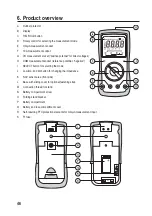
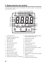
Page 46: ...measurement socket reference potential negative I SELECT button for selecting the mode J Low imp 400 k button for changing the impedance K NCV sensor area front side L Base with sliding cover for opt...

Page 47: ...imit current flow in the event of an overload and thus protect the multimeter and the current circuit The PTC protection elements reset themselves after tripping and a short cool down period For this...

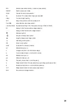
Page 48: ...cal current 12 Farad unit of electrical capacity 13 Degrees Celsius unit of temperature 14 Degrees Fahrenheit American unit of temperature 15 Display of the pulse duration of the positive half wave as...

Page 49: ...y for NCV function with voltage detection Diode test symbol Acoustic continuity tester symbol Capacity measurement range symbol Alternating current symbol Direct current symbol COM Connection for refe...

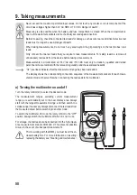
Page 50: ...levant regulations and the associated hazards OL overload indicates that the measurement range has been exceeded The display shows the corresponding connection sequence of the measurement sockets for...

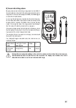
Page 51: ...A socket F and mA A socket E is swapped If the alarm is triggered and LEAd appears on the display check that the leads are connected to the correct sockets and that you have selected the correct measu...

Page 52: ...and the black measuring probe to the negative terminal The polarity of the measurement is indicated on the display After taking a measurement remove the leads from the meas ured object and switch the...

Page 53: ...mV range has an input resistance of 1000 M If open measuring inputs are used an undefined measurement value may be displayed in the mV range due to the high input resistance This however has no effect...

Page 54: ...t overload Do not measure any currents above 10 A in the 10A range and no currents above 600 mA in the mA A range otherwise the fuses trigger Perform the current measurement in the mA A measurement ra...

Page 55: ...COM mA A A 0 10 A COM 10A Insert the red test lead into the mA A or 10 A measurement socket Insert the black test lead into the COM meas urement socket Connect the two measuring probes de energised i...

Page 56: ...Measurement range Measurement sockets A 0 6000 A COM mA A mA 0 600 mA COM mA A A 0 10 A COM 10A Insert the red test lead into the mA A or 10 A measurement socket Insert the black test lead into the CO...

Page 57: ...DMM off g Measurement of pulse duration in The DMM can be used the ratio of the pulse duration of an alter nating voltage signal s positive half wave as a percentage of the entire period The maximum...

Page 58: ...the inherent resistance of the test leads does not affect the resist ance measurement The display should show 0 Auto range is thereby disabled Connect the measuring probes to the object that you want...

Page 59: ...fective Try tak ing the measurement again with the opposite polarity After taking a measurement remove the leads from the meas ured object and switch the DMM off j Continuity test Ensure that all obje...

Page 60: ...t G and the black lead into the COM socket H Due to the sensitive measuring input the display may show a reading even with open test leads Press the REL button to measure small capacities 600 nF The i...

Page 61: ...e The unit degrees Celsius C will appear on the display for the temperature measurement Insert the enclosed temperature sensor with the correct polar ity with the positive terminal in the V measuremen...

Page 62: ...s When no voltage is detected the display shows the abbrevia tion EF for electromagnetic field Disconnect all test leads from the multimeter No test leads are required for this function Switch the DMM...

Page 63: ...approx 1 s The display shows and the measure ment indicator is set to zero The automatic measurement range selection thereby disabled To disable this function change the measurement mode or press and...

Page 64: ...rotary control 11 Cleaning and maintenance a General information The multimeter should be calibrated once a year to ensure that measurements remain accurate The multimeter does not need to be service...

Page 65: ...d fuse compartment is open there is only access to the battery and fuses The casing no longer needs to be fully opened and disassembled This makes the multimeter safer and easier to use Proceed as fol...

Page 66: ...ry fuse compartment is open DANGER OF DEATH Do not leave flat batteries in the device Even leak proof batteries may corrode and destroy the device or release chemicals that are detrimental to your hea...

Page 67: ...tery fuse compartment Replace the defective fuse with a new fuse of the same type and nominal voltage The F1 fuse has the following values Ceramic high performance fuse FF 12 A 1000 V Dimensions 32 mm...

Page 68: ...to return all used batteries Battery Directive Batteries must not be placed in household waste Contaminated batteries rechargeable batteries are labelled with these symbols to indicate that disposal...

Page 69: ...connection with the display Is the hold function enabled Disable the hold function The multimeter cannot take measurements in the 10 A range Is the fuse in the 10 A input defective Check the F1 fuse...

Page 70: ...f 30 A Operating voltage 9 V block battery Operating conditions 0 to 40 C 75 RH Operating altitude max 2000 m above sea level Storage temperature 10 C to 50 C Weight approx 380 g Dimensions L x W x H...

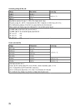
Page 71: ...erload protection Impedance 400 k max 250 V 3s The multimeter may display 10 counts if a measurement input is short circuited After using the LoZ feature leave the multimeter for 1 minute before using...

Page 72: ...before using it again TrueRMS peak Crest Factor CF 3 CF to 600 V TrueRMS peak for non sinusoidal signals plus tolerance CF 1 0 2 0 3 CF 2 0 2 5 5 CF 2 5 3 0 7 Direct current A DC Range Resolution Acc...

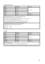
Page 73: ...ement 6A max 10 s at intervals of 15 minutes The multimeter may display 3 counts when a measurement input is open TrueRMS peak Crest Factor CF 3 CF over the entire range TrueRMS peak for non sinusoida...

Page 74: ...9 Hz 0 1 Hz 1 000 kHz 9 999 kHz 0 001 kHz 10 00 kHz 99 99 kHz 0 01 kHz 100 0 kHz 999 9 kHz 0 1 kHz 1 000 MHz 9 999 MHz 0 001 MHz 10 00 MHz 0 01 MHz Not specified The specified frequency range is 10 00...

Page 75: ...voltage detection Signal strength not specified Beep not specified Detection range approx 15 mm 50 mm Diode test Test voltage Resolution Approx 3 0 V DC 0 001 V Overload protection 600 V Test voltage...

Page 76: ...90 e Mesure du courant A 91 f Mesure de fr quence 94 g Mesure de la dur e d impulsion en 94 h Mesure de la r sistance 95 i Test de diodes 96 j Contr le de continuit 96 k Mesure de la capacit 97 l Mesu...

Page 77: ...t ches exigeantes du bricoleur ambitieux autant qu l utilisateur professionnel Voltcraft vous offre une technologie fiable un rapport qualit prix particuli rement avantageux Nous en sommes convaincus...

Page 78: ...fiche d alimentation Cette cat gorie comprend galement toutes les cat gories inf rieures telles que la CAT I pour la mesure des tensions de signal et de commande CAT III Cat gorie de mesure III pour l...

Page 79: ...ant ne doit pas d passer 600 V L entr e de mesure mA A est quip e de fusibles r armables PTC En cas de surcharge cela permet de limiter le flux de courant et de prot ger l appareil de mesure Cette fon...

Page 80: ...Le produit dans son ensemble ne doit pas tre modifi ou d mantel Lisez le mode d emploi attentivement et conservez le pour vous y r f rer ult rieurement Les consignes de s curit sont respecter imp rat...

Page 81: ...ons lectriques et aux mat riels prescrites par les syndicats professionnels L utilisation d appareils de mesure dans les coles centres de formation ateliers de loisirs et de r insertion ainsi que par...

Page 82: ...pourrait tre ainsi fauss e Lorsqu un fonctionnement sans risque de l appareil n est plus assur mettez l appareil hors service et assurez vous qu il ne pourra pas tre remis involontairement sous tensi...

Page 83: ...mesure COM potentiel de r f rence n gatif I Touche SELECT pour changer de fonction J Low Imp Touche 400 k pour commuter l imp dance K Surface de capteur NCV face avant L Socle avec cache coulissant po...

Page 84: ...protection PTC int gr s limitent le flux de courant et prot gent ainsi l appareil de mesure et le circuit lectrique En cas de d clenchement les l ments de protection PTC se r arment automatiquement a...

Page 85: ...esure de l intensit du courant lectrique 12 Farad unit de capacit lectrique 13 Degr Celsius unit de la temp rature 14 Degr Fahrenheit unit anglo saxonne de la temp rature 15 Affichage de la dur e d im...

Page 86: ...Symbole pour le testeur de continuit acoustique Symbole pour la plage de mesure de capacit Symbole pour le courant alternatif Symbole pour le courant continu COM Potentiel de r f rence de raccord de...

Page 87: ...initi es qui connaissent les consignes de s curit et qui sont inform s des dangers qui en r sultent Vous avez d pass la plage de mesure d s que OL pour Overload surcharge s affiche l cran Pour chaque...

Page 88: ...vertie entre la borne 10 A F et la borne mA A E Un signal sonore est alors mis et l indication LEAd fil de mesure s affiche l cran contr lez imm diatement les bornes utilis es ou la fonction de mesure...

Page 89: ...re noire au p le n gatif La polarit respective de la valeur mesur e s affiche avec la valeur mesur e instantan e sur l cran Quand la mesure est termin e d branchez les c bles de me sure de l objet mes...

Page 90: ...entr es de mesure sont ouvertes une valeur de mesure ind finie peut s affi cher sur la plage mV en raison de la r sistance d entr e lev e mais cela n a toutefois aucune influence sur le r sultat de la...

Page 91: ...ent donc d un dispositif de s curit contre les surcharges Ne mesurez en aucun cas des courants sup rieurs 10 A dans la plage de 10 A ou sup rieurs 600 mA dans la plage mA A sinon les fusibles pourraie...

Page 92: ...mA 0 600 mA COM mA A A 0 10 A COM 10A Branchez le cordon de mesure rouge dans la borne mA A ou 10 A Branchez le c ble noir dans la borne de mesure COM Raccordez en s rie les deux pointes de mesure hor...

Page 93: ...nction de mesure Plage de mesure Bornes de mesure A 0 6000 A COM mA A mA 0 600 mA COM mA A A 0 10 A COM 10A Branchez le cordon de mesure rouge dans la borne mA A ou 10 A Branchez le c ble noir dans la...

Page 94: ...esure de la dur e d impulsion en Le DMM peut afficher le rapport de la dur e d impulsion de la demi onde positive d un signal de tension alternative en pourcen tage pour l int gralit de la dur e de p...

Page 95: ...ce L affichage indique 0 La fonction Autorange est alors d sactiv e Raccordez maintenant les deux pointes de mesure l objet mesurer La valeur de mesure s affiche l cran condition que l objet mesurer n...

Page 96: ...interruption Effectuez une mesure contraire en guise de test Quand la mesure est termin e d branchez les c bles de mesure de l objet mesurer et teignez le DMM j Contr le de continuit Assurez vous que...

Page 97: ...borne COM H Lorsque les c bles de mesure ne sont pas prot g s il peut arriver qu une valeur s affiche l cran en raison de la sensibilit de l entr e de mesure Pour la mesure de petites capacit s 600 nF...

Page 98: ...dez comme suit Allumez le DMM et s lectionnez la fonction de mesure C L unit appara t l cran en degr s Celsius C pour la me sure de la temp rature Branchez la sonde de temp rature fournie en respecta...

Page 99: ...ion l cran affiche le sigle EF pour champ lectromagn tique Retirez tous les cordons de mesure de l instrument Pour cette fonction aucun cordon de mesure n est n cessaire Allumez le DMM et s lectionnez...

Page 100: ...la mesure se met z ro La s lection automatique des plages de mesure est d sactiv e ici Pour d sactiver cette fonction changez de fonction de mesure ou maintenez la touche de nouveau enfonc e pendant e...

Page 101: ...ormis un nettoyage occasionnel et le remplacement de fusibles ou de pile l instrument de mesure ne n cessite pas d entretien Vous trouverez ci apr s toutes les indications concernant le remplacement d...

Page 102: ...t le compartiment pile et fusibles est con u de fa on permettre uniquement l acc s la pile et aux fusibles Le bo tier ne doit plus tre ouvert com pl tement ni d mont Ces mesures renforcent la s curit...

Page 103: ...e laissez jamais des piles usag es dans l instrument de mesure car m me les piles prot g es contre les fuites peuvent s oxyder et ainsi lib rer des produits chimiques qui nuiront votre sant ou d truir...

Page 104: ...ible d fectueux par un fusible neuf du m me type et de m me intensit de courant nominal Le fusible F1 poss de les valeurs suivantes Fusible HPC c ramique FF 12 A 1000 V Dimensions 32 mm x 6 4 mm Refer...

Page 105: ...s les piles batteries usag es ordonnance relative l limination des piles batteries usag es il est interdit de les jeter dans les ordures m nag res Les piles batteries contenant des substances nocives...

Page 106: ...mauvaises bornes de mesure Comparez le branchement avec l affi chage sur l cran La fonction Hold est elle activ e D sactivez la fonction Hold La mesure dans la plage 10 A est impossible Le fusible de...

Page 107: ...utilisation pile 9 V Conditions d utilisation 0 40 C 75 rF Altitude de fonctionnement 2000 m max au dessus du niveau de la mer Temp rature de stockage de 10 C 50 C Poids env 380 g Dimensions L x l x...

Page 108: ...00 k max 250 V 3s Si l entr e de mesure est court circuit e il est possible que l cran indique un affichage 10 points Apr s utilisation de la fonction LoZ une dur e de r g n ration de 1 minute est n c...

Page 109: ...n cessaire Valeur de cr te TrueRMS Crest Factor CF 3 CF jusqu 600 V Valeur de cr te TrueRMS pour signaux non sinuso daux majoration de tol rance CF 1 0 2 0 3 CF 2 0 2 5 5 CF 2 5 3 0 7 Courant continu...

Page 110: ...15 minutes Si une entr e de mesure est ouverte il est possible que l cran indique un affichage de 3 points Valeur de cr te TrueRMS Crest Factor CF 3 CF sur l ensemble de la plage Valeur de cr te TrueR...

Page 111: ...kHz 0 001 kHz 10 00 kHz 99 99 kHz 0 01 kHz 100 0 kHz 999 9 kHz 0 1 kHz 1 000 MHz 9 999 MHz 0 001 MHz 10 00 MHz 0 01 MHz Non sp cifi La plage de mesure de fr quence sp cifi e est 10 00 Hz 10 MHz Niveau...

Page 112: ...de tension Affichage de la force du signal non sp cifi Signal sonore non sp cifi Distance de d tection env 15 mm 50 mm Test de diodes Tension d essai R solution env 3 0 V CC 0 001 V Protection contre...

Page 113: ...anningsmeting V 126 d LoZ spanningsmeting 127 e Stroommeting A 128 f Frequentiemeting 131 g Meting van de pulsduur in 131 h Meten van weerstand 132 i Diodetest 133 j Continu teitstest 133 k Capaciteit...

Page 114: ...er zelfs de moeilijkste taken probleem loos uitvoeren Voltcraft biedt u betrouwbare technologie met een uitstekende prijs kwaliteitsverhouding We zijn ervan overtuigd uw keuze voor Voltcraft is tegeli...

Page 115: ...nische apparaten die via een netstekker worden voorzien van netspanning Onder deze categorie vallen ook alle lagere categorie n bijv CAT I voor het meten van signaal en stuurspanningen CAT III Meetcat...

Page 116: ...erstellende PTC zekeringen Bij overbelasting wordt de stroom beperkt en het meetapparaat beschermd Daardoor valt bij deze meetfunctie het vervelende wisselen van zekering weg Een lage impedantie LoZ f...

Page 117: ...ct mag niet worden veranderd resp om gebouwd Lees de gebruiksaanwijzing goed door en bewaar deze om later nogmaals te kunnen raadplegen Neem altijd de veiligheidsinstructies in acht 4 Leveringsomvang...

Page 118: ...uit de buurt van kinderen worden gehouden Neem in industri le omgevingen deArbo voorschriften met betrekking tot het voorkomen van ongevallen in acht In scholen en opleidingsinstellingen hobby en werk...

Page 119: ...kan daardoor worden vertekend Als aangenomen mag worden dat veilig gebruik niet meer mogelijk is moet het apparaat worden uit geschakeld en tegen onbedoeld gebruik worden beveiligd Ga ervan uit dat ve...

Page 120: ...gatief potentiaal min I SELECT knop voor omschakelen van de functie J Low Imp 400 k knop voor omschakeling van de impedantie K NCV sensoroppervlak kopse kant L Aansluiting met schuifafdekking voor opt...

Page 121: ...de zekering te vervangen De inge bouwde PTC zekeringen beperken in geval van overbelasting de stroom en beschermen zo het meetapparaat en het stroomcircuit De PTC zekeringen worden nadat deze werden g...

Page 122: ...micro macht 6 11 Amp re eenheid voor elektrische stroom 12 Farad eenheid van elektrische capaciteit 13 Graden Celsius Europese temperatuureenheid 14 Graden Fahrenheit Amerikaanse temperatuureenheid 15...

Page 123: ...mbool voor de diodetest Symbool voor de akoestische continu teitstest Symbool voor het capaciteitsmeetbereik Symbool voor wisselstroom Symbool voor gelijkstroom COM Meetaansluiting referentiepotentiaa...

Page 124: ...met de geldende voorschriften en de eruit voortvloeiende gevaren Zodra er OL Overload overbelasting op het display verschijnt hebt u het meetbereik overschreden Voor elke meetfunctie wordt de juiste...

Page 125: ...ussen de 10A bus F en de mA A bus E verwisseld is Klinkt er een geluidssignaal en verschijnt er LEAd meetkabel op het display controleer dan onmiddellijk de aansluitingen en de ingestelde meetfunctie...

Page 126: ...e zwarte meetpen is de negatieve pool De polariteit van de meetwaarde wordt samen met de actuele meetwaarde weergegeven op het display Verwijder na het meten de meetkabels van het te meten object en z...

Page 127: ...mV spanningsbereik heeft een ingangsweerstand van 1000 M Bij open meetingangen kan in met mV bereik vanwege de ingangs weerstand een ongedefinieerde meetwaarde worden weergegeven die echter geen invl...

Page 128: ...ligd tegen overbelasting Meet op het bereik 10 A in geen geval stromen van meer dan 10 A resp in het mA A gebied stro men groter dan 600 mA anders spreken de zekeringen aan Voer de stroommeting in het...

Page 129: ...COM mA A A 0 10 A COM 10A Steek de rode meetkabel in de mA A of 10A meetbus Steek de zwarte meetkabel in de COM meetbus Verbind nu de twee meetpennen stroomvrij in serie met het te meten object batter...

Page 130: ...rende meetbussen Meetfunctie Meetbereik Meetbussen A 0 6000 A COM mA A mA 0 600 mA COM mA A A 0 10 A COM 10A Steek de rode meetkabel in de mA A of 10A meetbus Steek de zwarte meetkabel in de COM meetb...

Page 131: ...ct en zet de DMM uit g Meting van de pulsduur in De DMM kan de verhouding van de pulsduur de positieve halve golflengte van een wisselspanning signaal in procent van de ge hele periode weergeven Het m...

Page 132: ...gende weerstandsmeting Het display geeft 0 weer Autorange wordt hierbij gedeactiveerd Verbind nu de twee meetpennen met het te meten object Als het gemeten object niet hoogohmig is of wordt onderbroke...

Page 133: ...erd om UR gemeten of is de diode defect onderbro ken Voer ter controle nog een meting met omgekeerde polen uit Verwijder na het meten de meetkabels van het te meten object en zet de DMM uit j Continu...

Page 134: ...de V meetbus G en de zwarte meetkabel in de COM meetbus H Op basis van de gevoelige meetingang kan bij open meetkabels een weergave op het display verschijnen Druk voor het meten van kleine capaciteit...

Page 135: ...Zet de DMM aan en selecteer de meetfunctie C Op de dis play verschijnt de eenheid van graden Celsius C voor de temperatuurmeting Sluit het meegeleverde thermokoppel juist aan door de plus stekker in...

Page 136: ...der spanningsdetectie de letters EF weer elektromagnetisch veld Verwijder alle meetkabels van uw meetapparaat Voor deze functie zijn er geen meetkabels nodig Zet de DMM aan en selecteer de meetfunctie...

Page 137: ...t op nul gezet De automatische meetbereikkeuze wordt hierbij gedeactiveerd Om deze functie uit te schakelen schakelt u om naar een andere meetfunctie of houdt u de toets nogmaals ongeveer 1 seconde in...

Page 138: ...durende een lange periode te garanderen moet deze eenmaal per jaar worden gekalibreerd Het meetapparaat is onderhoudsvrij met uitzondering van incidentele reiniging evenals vervanging van batterijen e...

Page 139: ...tterij en zekeringvak open staat men alleen toegang heeft tot de batterij en de zekeringen De behuizing hoeft niet zoals gebruikelijk volledig te worden geopend en gedemonteerd Deze maatregelen verhog...

Page 140: ...t geen lege batterijen in het meetapparaat zitten Zelfs bij lekbestendige batterijen kan corrosie optreden waardoor er chemicali n uit kunnen lekken die schadelijk zijn voor de gezondheid en het appar...

Page 141: ...cte zekering door een nieuwe zekering van hetzelfde type en nominale stroomsterkte De zekering F1 heeft de volgende kenmerken Hoogwaardige keramische zekering FF 12 A 1000 V Afmetingen 32 mm x 6 4 mm...

Page 142: ...ijk verplicht om alle lege batterijen accu s in te leveren Batterijen accu s mogen niet met het huisvuil meegegeven worden Batterijen en accu s met schadelijke stoffen worden gekenmerkt door de hierna...

Page 143: ...functie Zijn de verkeerde meetbussen gebruikt Vergelijk de aansluiting met de indicatie op het display Is de Hold functie geactiveerd Schakel de Hold functie uit Geen meting in het 10A meetbereik mog...

Page 144: ...jfsspanning 9V blokbatterij Gebruikscondities 0 tot 40 C 75 rel vochtigheid Gebruikshoogte max 2000 m boven NAP Opslagtemperatuur 10 C tot 50 C Gewicht ca 380 g Afmetingen l x b x h 178 x 85 x 40 mm M...

Page 145: ...ingsbeveiliging 600 V impedantie 400 k max 250 V 3s Bij een kortgesloten meetingang is een weergave van 10 counts mogelijk Na het gebruik van de LoZ functie is een hersteltijd van 1 minuut nodig Wisse...

Page 146: ...ueRMS piekwaarde Crest Factor CF 3 CF tot 600 V TrueRMS piekwaarde voor niet sinusvormige signalen plus tolerantie CF 1 0 2 0 3 CF 2 0 2 5 5 CF 2 5 3 0 7 Gelijkstroom A DC Bereik Resolutie Nauwkeurigh...

Page 147: ...continu meten 6 A max 10 s met tussenpauze van 15 minuten Bij een open meetingang is een weergave van 3 counts mogelijk TrueRMS piekwaarde Crest Factor CF 3 CF over het gehele bereik TrueRMS piekwaar...

Page 148: ...z 1 000 kHz 9 999 kHz 0 001 kHz 10 00 kHz 99 99 kHz 0 01 kHz 100 0 kHz 999 9 kHz 0 1 kHz 1 000 MHz 9 999 MHz 0 001 MHz 10 00 MHz 0 01 MHz Niet gespecificeerd Het gespecificeerde frequentiemeetbereik b...

Page 149: ...detectie Weergave signaalsterkte niet gespecificeerd Signaaltoon niet gespecificeerd Detectieafstand ca 15 mm 50 mm Diodetest Testspanning Resolutie ca 3 0 V DC 0 001 V Overbelastingsbeveiliging 600 V...

Page 150: ...150...

Page 151: ...151...

Page 152: ...e time of printing Copyright 2018 by Conrad Electronic SE Ceci est une publication de Conrad Electronic SE Klaus Conrad Str 1 D 92240 Hirschau www conrad com Tous droits r serv s y compris de traducti...

Reviews: