background image

4.15. Results Printing ..............................................................................66


4.16. Results Export ................................................................................68


4.17. Exiting from the IEC1000-3 Software ...........................................68


5. On-Line Help ............................................................. 69


6. Reference Information.............................................. 73


6.1. How the Analyser Performs a 2001 Edition Harmonics Test..........73


6.2. Glossary of Terms ............................................................................76


6.3. Equipment without limits .................................................................79


6.4. Control Methods Not Allowed.........................................................79


6.5. IEC61000-3-2 2001 harmonics test duration ...................................81


6.6. Harmonic Test Conditions IEC61000-3-2 2001 ..............................82


6.7. Flicker Test Conditions IEC61000-3-3  2001..................................88


Summary of Contents for PM3000ACE

Page 1: ...IEC61000 3 HARMONICS FLICKER SOFTWARE FOR THE PM3000ACE USER MANUAL VPN 98 025 Issue 7 August 2006 ...

Page 2: ...tion may be reproduced stored in a retrieval system or transmitted in any form or by means electronic mechanical photocopying recording or otherwise without prior written permission of Voltech Instruments All rights reserved Voltech Instruments 1997 2006 Microsoft Windows and the Windows logo are either registered trademarks or trademarks of Microsoft Corporation in the United States and or other ...

Page 3: ...one of the Voltech main offices listed below and ask for assistance Voltech Instruments Ltd 148 Sixth Street Harwell International Business Centre Harwell Didcot Oxon OX11 0RA UK Tel 44 0 1235 834555 Fax 44 0 1235 835016 applications voltech co uk Voltech Instruments Inc 11637 Kelly Road Suite 306 Fort Myers FL 33908 USA Tel 1 239 437 0494 Fax 1 239 437 3841 applications voltech com ...

Page 4: ......

Page 5: ...Software 21 3 6 Transferring the Software to a Different PC 22 3 7 Setting up your IEEE488 interface card 23 4 Getting Started 26 4 1 Starting the Software 26 4 2 Setting Up the Test Equipment 26 4 3 Set up Power Analyzer and AC Source Communications 27 4 4 Setup AC Source 30 4 5 Power Analyzer Shunt and Scaling 33 4 6 Entering a New Product 34 4 7 Configuring a Fluctuating Harmonics Test 37 4 8 P...

Page 6: ...ce Information 73 6 1 How the Analyser Performs a 2001 Edition Harmonics Test 73 6 2 Glossary of Terms 76 6 3 Equipment without limits 79 6 4 Control Methods Not Allowed 79 6 5 IEC61000 3 2 2001 harmonics test duration 81 6 6 Harmonic Test Conditions IEC61000 3 2 2001 82 6 7 Flicker Test Conditions IEC61000 3 3 2001 88 ...

Page 7: ...section of the Help menu 1 1 STANDARDS IMPLEMENTED BY THIS SOFTWARE Together with the Voltech PM3000ACE this software tests to the standards listed below As these standards are under constant review it is the responsibility of the user to ensure that the correct version of a standard is being used This is usually the most recent version of the standard available For the most up to date guidance an...

Page 8: ...001 Latest date of publication July 2001 Date of withdrawal of previous standards January 2004 This edition of the standard incorporates Amendment 4 also referred to as prA14 which radically alters the way in which the harmonic limits are applied IEC61000 4 7 2001 Testing and measurement techniques The PM3000ACE and this software only comply with the transitional allowances which will be withdrawn...

Page 9: ... 61000 4 15 replaced IEC60868 in 2003 PM3000ACE Firmware v2 19 or greater is REQUIRED for compliance testing Standards The standards discussed here are published by the IEC www iec ch and implemented by national bodies such as BSI www bsi org uk Copies may be purchased from them and it is always the users responsibility to ensure that they are making measurements in accordance with the regulations...

Page 10: ...C61000 3 2 are different different results will be obtained and different views of those results are possible Throughout the software and this user manual the following conventions are used IEC61000 3 2 1995 Incorporating Amendment No 1 is referred to as IEC61000 3 3 1995 or the 1995 version IEC61000 3 2 Ed 2 2001 is referred to as IEC61000 3 2 2001 or the 2001 version This edition incorporates th...

Page 11: ... only does the software allow you to quickly set up the tests to be done but it then also goes on to control the ac source and Power Analyzer to make the measurements It then reads back the measurement data and presents the results in easy to read tables and graphs including comparisons with the specification limits and highlighting the Passes and Fails When the test is finished all results can be...

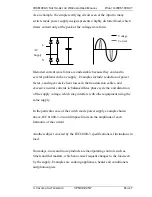
Page 12: ...nnected 2 1 BACKGROUND Historically the need for IEC61000 3 has come about due to the increased use of electronic circuits in controlling the power taken by products from the ac supply Before the advent of power electronics most loads connected to the ac supply lines were resistive e g filament lamps and heaters or inductive e g fixed speed ac motors The currents taken by such loads are sinusoidal...

Page 13: ...he transmission cables and excessive neutral currents in balanced three phase systems and distortion of the supply voltage which may interfere with other equipment using the same supply In the particular case of the switch mode power supply example shown above IEC61000 3 2 would impose limits on the amplitude of each harmonic of the current Another subject covered by the IEC61000 3 specifications ...

Page 14: ...fluctuating source voltage being presented to the other appliances connected to the same distribution point Of crucial importance is the effect caused by the changing supply voltage in the light output of a filament lamp This output is proportional to the square of the source voltage and therefore even small changes of voltage can cause significant changes in light intensity The effect on a human ...

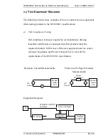
Page 15: ...est laboratories offering traceable certification to customers that their products meet the required standard In this case all the test equipment used ac source reference impedance and Power Analyzer has to meet all the requirements of the IEC61000 3 specification Harmonic Current Measurements Flicker and Voltage Deviation Measurements Equipment Required N L Source Impedance AC Source AC Source V ...

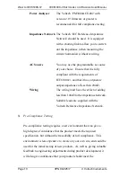
Page 16: ...e requirements of IEC61000 3 and that it has a dynamic output impedance of less than 20mΩ Wiring The wiring must have the effect of adding less than 10mΩ to the impedance network Suitable leads are supplied with the Voltech Reference Impedance Network b Pre Compliance Testing Pre compliance testing requires a test environment that can give a high degree of confidence that the product meets the req...

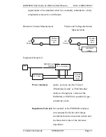
Page 17: ...red Power Analyzer Again you may use the Voltech PM3000ACE 002 or PM3300 002 Analyser though any version of the PM3000A or PM3300 is suitable for pre compliance work Impedance Network Not needed as the PM3000A Analyser can compute the flicker and voltage deviations from the measured current and the theoretical value of the reference impedance N L AC Source AC Source V A PC Power Analyser Product U...

Page 18: ...61000 3 Software includes voltage source qualification the quality of your source is known at all times In general if your product meets the standard with a good margin when testing with your ac line voltage there should be no problems when you submit it for fully compliant testing Wiring Without the measurement of voltage drop across the Impedance Network the requirement for very low impedance wi...

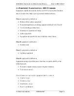
Page 19: ...ipment defined to be Class D Tools excluding portable tools Dimmers for incandescent lamps Audio equipment Equipment not specified in one of the three other classes Class B equipment is defined as Portable tools Class C equipment is defined as Lighting equipment Class D equipment is defined as Equipment having a specified power less than or equal to 600W of the following types Personal computers a...

Page 20: ...INDOWS USER MANUAL Page 14 VPN 98 025 7 Voltech Instruments Harmonic spectrum including phase Can be shown to have a pronounced effect on the public electricity supply system Such equipment may be reclassified in a future edition of the standard ...

Page 21: ... 2 Does the equipment use techniques not allowed by section 6 1 Control Methods Not Allowed Yes Professional equipment Yes May require permission to connect See IEC61000 3 4 No No Does not conform 3 Do the exceptions of Clause 7 Equipment Without Limits or Annex C apply Yes Conforms No 4 Are specific test conditions defined in Annex C2 Yes Use those conditions No Use the generic conditions of Clau...

Page 22: ... of the standard are mainly in the way that the harmonic results are manipulated and compared to these limits Maximum Permitted Harmonic Current Harmonic n Class A Amps Class B Amps Class C of Fund Class D mA W Odd Harmonics 3 2 30 3 45 30 x λ 3 4 5 1 14 1 71 10 1 9 7 0 77 1 155 7 1 0 9 0 40 0 60 5 0 5 11 0 33 0 495 3 0 35 13 0 21 0 315 3 3 85 13 15 n 39 0 15 x 15 n 0 225 x 15 n 3 3 85 n Even Harm...

Page 23: ...R WINDOWS USER MANUAL WHAT IS IEC61000 3 Voltech Instruments VPN 98 025 7 Page 17 3 For Class D the limits vary with the power consumed and are specified as either the mA W limit or the Class A limit whichever is the smaller ...

Page 24: ...armonics 1kb per measurement Fluctuating Harmonics 7Mb per hour Flicker 5kb per 10 minutes IMPORTANT Your Voltech IEC61000 3 software operates in Real Time This means that during execution of a test limits and results are being computed and displayed simultaneously The demands of this type of electrical test and analysis mean that a large amount of data must be transferred quickly from your Voltec...

Page 25: ...ystem agent should be disabled 3 Networking shares should be disabled or remain inactive A network user accessing the PCs local disk or printer may interrupt communications 4 Do not use the host PC for any type of shared printer 5 Disable any internal modem that has auto answer features 3 2 IEEE 488 INTERFACE CARDS SUPPORTED IOtech Personal 488 GP488B National Instruments GPIBII IIA CEC 488 Most o...

Page 26: ...3000ACE Information IEC Harmonics Flicker Software to install the software If the software was provided electronically the run IEC61000 Software for PM3000 exe Follow the on screen instructions The default directory for the IEC61000 3 for Windows software is C Program Files Voltech Instruments Voltech IEC 61000 Software for PM3000 You may choose an alternative drive directory when prompted during ...

Page 27: ...tware will not communicate with a Power Analyzer until it has been registered You may however browse and print the example results supplied before the software is registered To register the software Install the software on the PC where it is intended to be used as above Look at the registration details found under Registration from the Help menu This dialogue will display an ID Code which is uniqu...

Page 28: ...e software will now operate The Key Code demo or full version is not time related and may be entered at any time after you have sent the ID Code to Voltech 3 6 TRANSFERRING THE SOFTWARE TO A DIFFERENT PC The software is licensed for use on one PC only At Voltech s discretion it is possible to occasionally transfer the licence to a different PC To transfer the licence Install a copy of the software...

Page 29: ...I Before installing the Personal 488 card into your PC make a note of the following Type of card GP488B IRQ level Set by jumpers on the card factory default setting 7 DMA channel Set by jumpers on the card factory default setting 1 Memory address Set by switches on the card factory default setting 02E1 Switch off the PC and follow the instructions given in your IOtech user manual to install the in...

Page 30: ...using Windows File Manager select the and run the file C WINDOWS IEEE488 DRVR488W EXE You can now run the IEC61000 3 for Windows Software Between runs of the IEC61000 3 for Windows Software it is recommended that you exit from and close down Windows and then start Windows again to reset the IOtech drivers before re starting the IEC61000 3 Software Note If you find difficulty in getting the IOtech ...

Page 31: ...river Disk 1 of 2 into drive A From the Windows Program Manager using the mouse Pull down the File menu Click on Run In the Run dialogue box on the Command Line type A SETUP and click on the OK button After the setup program has finished you can run the IEC61000 3 for Windows Software CEC 488 Switch off the PC and follow the instructions given in your CEC user manual to install the interface card ...

Page 32: ... or IEEE 488 In many cases you will be able to use a single test rig for the evaluation of a number of different products to the IEC61000 3 specification Therefore the IEC61000 3 software has a Setup menu which allows you to configure the test equipment and the type of test to perform first PC to PM3000 Connections To communicate between the PC and the PM3000 either RS232 or IEEE 488 communication...

Page 33: ...baud PM3000 to Equipment Under Test Connections The PM3000 needs to be connected to the equipment under test to measure both the voltage and the current Even for fluctuating harmonics testing which is a current measurement the voltage source is measured One easy way to connect break the conductor carrying the power to the equipment under test is to use one of Voltech s Break Out boxes They come wi...

Page 34: ... Analyzer and click on the OK button Alternatively if you are using a serial interface click with the mouse on the RS232 button enter the appropriate Comm Port and Baud Rate and then click the OK button Having set up the communications interface for the Power Analyzer clicking OK will return you to the Top Level menu from where you can select Setup Communications AC Source ...

Page 35: ... GETTING STARTED Voltech Instruments VPN 98 025 7 Page 29 to similarly set up the communications interface for the test source This obviously would not be necessary if you were using the available mains supply instead of a programmable ac source ...

Page 36: ...rce At the next dialogue box you can choose to have the software automatically control an AC Source or to use the normal line supply Mains manually controlled source Using the normal mains AC line supply or manually controlling an AC Source Select Mains AC line and click on OK The software will prompt for AC Source ON and OFF during testing Automatic control of a programmable AC Source ...

Page 37: ...utput ON and OFF to the desired voltage and frequency during testing If the AC source model you are using is listed simply select it and click on OK To configure an AC Source that is not listed select Add New AC Source To edit the details of an existing source select the source and then choose Edit AC Source For both of the above you will see the same Configure AC Source dialogue To delete a sourc...

Page 38: ...30V is necessary Range and output impedance commands may be required to set some sources up correctly Source command delay Enter here a time in milliseconds if you are experiencing communications problems It is possible for the software to issue consecutive commands before a source is ready for them If in doubt start with a long delay 1000mS and shorten the delay if required Source ON OFF prompt B...

Page 39: ... directly It is possible to use the analyzer with external voltage or current transducers to extend the measurement range From the Top Level menu using the mouse select Setup Shunt Scaling to bring up the following dialogue box If the transformer is not 1 1 you should enter the appropriate current or voltage scaling factor before clicking on OK If you are using a current shunt external to the Powe...

Page 40: ... Level menu 4 6 ENTERING A NEW PRODUCT The IEC61000 3 Standard is concerned with the testing and certification of products Therefore to enable you to set up and run a program of tests for each product the IEC61000 3 software organises its results files identified by the name of the product under test The first task for you to do when starting a series of tests on a new product is to enter the data...

Page 41: ... characters The working Drive and Directory where the data is to be stored If required use the Network button to access more drives connected to your network For the Description and the Serial Number you can use any of the keyboard characters in any order including both upper and lower case alpha characters Similarly for the Title you can again use any of the keyboard characters in any order but a...

Page 42: ...he Operating Voltage 230V The Current Range 1A Which Standard is to be applied IEC61000 2001 This version of the standard is recommended for all new equipment For features of IEC61000 3 2 1995 testing see the help system of the software Which Channel of the PM3000A or PM3300 will be used for measurement Channel 1 The data in parenthesis are the values chosen in the case of PS123 ...

Page 43: ...p Select the Class A B C or D that the equipment belongs to See Chapter 2 The correct limits will automatically be chosen The other possible entries into this dialogue are described below Once the dialogue entries are complete click on Ok and close the product configuration dialogue The product is now ready to test Class C Limits There are three possible types of limit that can be applied to Class...

Page 44: ...Class C less or equal to 25 W There are 2 possible limits that may be applied 1 The Class D limits OR 2 The limits below as long as the current waveform meets certain criteria for its shape Note that these criteria are completely different to the waveform shape checking used for Class D in a previous edition of the standard The waveform shall be such that it begins to flow before or at 60 degrees ...

Page 45: ...the limits The analyzer automatically measures fundamental input current in accordance with the required measurement methods and displays the result The measured fundamental input current can then be entered retrospectively and the limits re computed IEC61000 3 2 2001 Waveform Check For a waveform check the analyzer performs a waveform datalog and displays one cycle of the voltage and current This...

Page 46: ... C is selected this field is inactive IEC61000 3 2 2001 Specified Power The power of the equipment under test as specified by the manufacturer The specified power is used to calculate limits for Class D and some Class C tests This field is inactive when Class A or Class B is selected The power must be determined using the methods detailed below If the power is unknown it will be measured by the an...

Page 47: ... by the manufacturer In the event that the measured value is outside of this tolerance band about the specified value the measured power shall be used to establish limits IEC61000 3 2 2001 Fundamental Current The fundamental current is used to calculate some Class C limits This field is inactive when Class A B or D is selected The fundamental input current is defined to be the maximum of the measu...

Page 48: ... test has been configured choose Fluctuating Harmonics from the Run Test menu and the software will automatically configure the analyzer and AC Source For a manual source you will be prompted to Switch the Mains on Now Once the system is ready you will see the following dialogue Click on Start to begin the test In accordance with the standards the first 10 seconds of the test will be ignored The e...

Page 49: ... second period the PC will display the latest harmonics reading in real time At the end of the test the software will automatically reset the analyzer and AC Source If you are using a manual AC Source you will be prompted to switch it off You must then save the results using the filename and directory of your choice ...

Page 50: ...tle Serial Number and Description From those originally entered when the product was configured You will then be presented with a summary of the test results See the next section for a description of the possible result views for fluctuating harmonics 4 9 CHANGING TEST DETAILS When a fluctuating harmonics result is open see below the test details Class limit and user entered data may be changed at...

Page 51: ...harmonics test to be re classified and compared against revised limits and saves you from having to make pre tests to determine for example maximum watts 4 10 VIEWING RESULTS At the end of a test or by opening a result several different result and diagnostic views are available To open a previously saved result select Result Open to see this dialogue ...

Page 52: ...nstruments Select the Result Type Fluctuating Harmonics in this example locate the result you wish to open and double click on it 4 11 VIEWING FLUCTUATING HARMONICS RESULTS The default view that is opened is the Summary Results view The views available below the View menu are described below ...

Page 53: ... VPN 98 025 7 Page 47 Summary Results This is a summary test report showing the overall test PASS FAIL together with all the product and test details The first 3 sections of this report will automatically appear at the top of the printout of any of the other result views available ...

Page 54: ...harmonic readings and the maximum individual smoothed harmonic readings compared to the limits In the example above the results for harmonic 5 show that the average result has exceeded limit 1 but not limit 2 and that the maximum reading has not exceeded limit 2 resulting in a FAIL for harmonic 5 See the reference information for more details ...

Page 55: ...es are available Each displays 40 harmonics along the bottom with a bar above representing the amplitude of the harmonic Linear Worst Case Shows the maximum amplitude of each of the individual smoothed harmonics Average Vs Limit 1 Shows the average value of each harmonic compared to Limit 1 A red bar indicates a failure ...

Page 56: ...lues for the individual smoothed harmonics during the test compared to their limit The data is the same as that presented in the Linear Worst Case view but in this Normalized view Limit 1 is scaled to equal 1 and the same scale factor is used to display Limit 2 and the worst case harmonic This view shows how close a harmonic is to its limit irrespective of the size of the limit ...

Page 57: ...own together with limits 1 and 2 Use the play and pause keys to scan through each reading automatically or use the less than and greater than keys of the keyboard to scan through the readings one at a time Normalized All This view shows each of the 16 cycle block readings as above with the limits normalised This view shows how close a harmonic is to its limit irrespective of the size of the limit ...

Page 58: ...plitude of the selected harmonic during the duration of the test Limit 1 and Limit 2 for that harmonic are also shown At the top of the main window the reading number amplitude is shown that correspond to the position of the red marker Click anywhere on the trace to re position the marker Use the less than and greater than keyboard keys to view the different harmonics Harmonic 7 Reading 19 0 10361...

Page 59: ...rison The maximum measured watts should be within 10 of the user specified watts Click anywhere on this window to move the red marker and view details for the associated reading at the top of the main window Amps and Power Factor This view shows the fundamental input current amps and power factor as they varied during the test together with their user specified levels See the reference information...

Page 60: ...ecking see the reference information Measurement of THC is not a specific requirement of the standard other than in the absence of specific guidelines emission tests shall be conducted with the user s operation controls or automatic programs set to produce the maximum THC under normal operating conditions Click anywhere on this window to move the red marker and view details for the associated read...

Page 61: ...a repeatability test performed This test is found under the result menu To select results to test for repeatability click on your first choice using the mouse and then hold the CTRL key when mouse clicking on the others The list of results selected appear in the Results Description box Click on OK to run the repeatability test The repeatability test compares all the harmonic results for each harmo...

Page 62: ...ving the repeatability result a summary table of the chosen results is shown together with a PASS or FAIL for repeatability If the test fails some of the maximum differences are shown Should the repeatability test fail ensure that the results selected refer to the same product tested under identical conditions ...

Page 63: ...t for the power supply PS123 again connect it into the test rig as shown below Again it will be assumed that you are using the available Mains supply To set up the parameters for the flicker measurement From the Top Level menu using the mouse select Product Configure At the next dialogue box V A PC Power Analyser AC Source or Mains PS123 Product Under Test ...

Page 64: ... assuming that this time you want to use the measurement rig shown above for pre compliance testing click on the Current button in the Measurement Method box the Resistance and Reactance default to the normal values specified in the IEC61000 3 3 Standard For the 2001 edition of the standard The dc limit is 3 3 The dt limit is 500mS the time for which the voltage characteristic exceeds a voltage ch...

Page 65: ...r day AND has EITHER a delayed restart 10 s of seconds OR Manual restart after power supply interruption Choose Attended or switching 2 day to automatically set up this limit The Pst limit is 1 The Plt limit is 0 65 The N value must be 12 The test duration must be 10 minutes for a Pst test and should be 120 minutes 2 hours for a Plt test See the software help system for details of flicker test lim...

Page 66: ...Flicker Meter to bring up a sequence of dialogue boxes including the following As for the Fluctuating Harmonics test ensure that the Mains supply is connected to the Product Under Test at the first display and click on the OK button At the second display ensure that the Product Under Test is switched on and has settled into steady state operation and then click on the Start button ...

Page 67: ...TWARE FOR WINDOWS USER MANUAL GETTING STARTED Voltech Instruments VPN 98 025 7 Page 61 The measurements will commence and displays similar to the following will be seen When the measurements are finished you will see ...

Page 68: ...ished and the result is displayed as a table Again you can use the View menu to bring up an alternative graphical presentation the Pst curves There will be a series of Pst curves one for each ten minute period in the measurement You may view each curve in turn by using the less than and greater than keys to scroll through the series If you wish to compare two or more results from the Top Level men...

Page 69: ...ng on the d button this will bring up a list of available results in the Result Description box Finally select the required result from the list by double clicking with the mouse This will close the dialogue box and add the selected result to those already on view To remove a result from the display simply select that result window by clicking on it with the mouse and then from the Top Level menu ...

Page 70: ... perform this measurement 24 measurements of dmax are made each of one minute duration For each one minute period The measurement is started The equipment under test is switched on soon after the measurement is started The equipment under test is switched off before the end of the 1 minute period after operating for as long as possible but in sufficient time for all moving parts inside the EUT to ...

Page 71: ...minute test period and an OFF prompt before the end of a one minute period These are for guidance only you may switch the equipment under test On and then Off once at any time during the test as long as you adhere to the guidelines above The values of dc and dt are shown for information only At the end of the 24 1 minute tests you are prompted to save the results and then the overall test result i...

Page 72: ...TING If you wish to print results first open the result you wish to print and then click on Result Print Preview to check that all is satisfactory Then click on the Print button to start printing Standard windows printing commands are available in the print options All printers supported by windows drivers can be used ...

Page 73: ...RE FOR WINDOWS USER MANUAL GETTING STARTED Voltech Instruments VPN 98 025 7 Page 67 Print Header Option This option can be found under the Result menu The print header will appear at the top of the page on all printouts ...

Page 74: ...and directory where the exported results will be stored You may export all of the available data in a form comma separated variable that is suitable for import into common spreadsheet applications Since a large number of results are produced every second of a fluctuating harmonics test the exported file may be very large for tests of a long duration 4 17 EXITING FROM THE IEC1000 3 SOFTWARE When yo...

Page 75: ...Started examples of the previous section To assist you to make full use of its capabilities while you are actually running tests the IEC61000 3 Software is equipped with extensive on line help To access the on line help from the Top Level menu select Help Contents The Contents display is the starting point for many pages of on line help which function in the same way as any software package runnin...

Page 76: ... Page 70 VPN 98 025 7 Voltech Instruments For example click on the words Step by Step User Guide to lead on to At the above display click on the words of the topic of interest to bring up the help dialogue Alternatively click on the Search button to move to ...

Page 77: ...ments VPN 98 025 7 Page 71 Using the mouse scroll to the select a word from the central list and click on the Show Topics button Select a topic from the lower list and click on the Go To button to bring up the required help text When you have finished with the on line help ...

Page 78: ...ON LINE HELP IEC61000 3 SOFTWARE FOR WINDOWS USER MANUAL Page 72 VPN 98 025 7 Voltech Instruments select File Exit to return to the IEC61000 3 Software Top Level menu bar ...

Page 79: ...nts shall be performed as follows For each harmonic order measure the 1 5 s smoothed rms harmonic current in each DFT time window This is the same method used in previous versions The analyzer calculates all 40 harmonic amplitudes every 16 cycles of the supply waveform without gaps or overlap Each of the 40 harmonic amplitudes is smoothed by a filter with a 1 5 second time constant Calculate the a...

Page 80: ... whichever is greater are disregarded 4 For the 21st and higher odd order harmonics the average values obtained for each individual odd harmonic over the full observation period calculated from the 1 5s smoothed rms values may exceed the applicable limits by 50 provided that the measured POHC does not exceed the POHC which can be calculated from the applicable limits all 1 5 s smoothed rms individ...

Page 81: ...rd small values and compare to the limits That s 39 averages compared to the limits ALSO 3 If the any of the odd average harmonics from 21 to 39 measured in 2 exceed the limit that s OK as long as The measured POHC for each 16 cycle block does not exceed the POHC calculated from the limits AND Condition 1 is still met The combination of Voltech PM analyzer and associated software perform all the n...

Page 82: ...power must be determined using the methods detailed below If the power is unknown it will be measured by the analyzer and this value can be entered retrospectively at the end of the tests and the limits re computed accordingly from 6 2 2 of the standard The value of input power to be used for calculation of limits shall be determined as follows measure the 1 5s smoothed active input power in each ...

Page 83: ...o establish limits If the specified power is unknown it will be measured by the analyzer and this value can be entered retrospectively at the end of the tests and the limits re computed accordingly IEC61000 3 2 2001 Fundamental Current The fundamental current is used to calculate some Class C limits This field is inactive when Class A B or D is selected The fundamental input current is defined to ...

Page 84: ...he limits re computed accordingly POHC Partial odd harmonic current is the total rms value of the odd harmonic components of orders 21 to 39 POHC is used during the application of limits THC Total harmonic current is the total rms value of the harmonic components of orders 2 to 40 Although the measurement of THC is not specifically required by the standard the standard requires that emission tests...

Page 85: ...THODS NOT ALLOWED From section 6 1 of the standard The following restrictions apply even to equipment to which no harmonic current limits apply as defined in clause 7 a asymmetrical controls according to IEV 161 07 11 except where they are the only practical solution to detect unsafe conditions b half wave rectification directly on the mains supply except where it is the only practical solution to...

Page 86: ... less than or equal to 200W or that the limits of table 3 are not exceeded Domestic equipment with symmetrical control used for a short time for example hair dryers shall be tested under Class A Even though asymmetrical controls and half wave rectification are permitted under the conditions given above the equipment shall still comply with the harmonic requirements of this standard ...

Page 87: ...od or sufficient duration to meet the requirements for repeatability The cycle of operation of the equipment plus a few seconds 10 secs minimum Random Sufficient duration to meet the requirements for repeatability 2 5 minutes and check repeatability Long cyclic Tcycle 2 5 min Full equipment program cycle reference method or a 2 5 minute period considered the operating period with the highest THC F...

Page 88: ...ent limits specified in clause 7 apply to line currents and not to currents in the neutral conductor The equipment is tested as presented by and in accordance with information provided by the manufacturer Preliminary operation of motor drives by the manufacturer may be needed before the tests are undertaken to ensure that results correspond with normal use Test conditions for television receivers ...

Page 89: ...nce made to the white level and 100 saturation b Monochrome television Radio frequency signal a full TV signal with modulated picture and sound carrier Sound modulation see Item a above The picture modulation is a monochrome test pattern with a black and white level according to Item a and an average overall picture content of 50 of the reference white level C 2 2 2 The receiver shall be tuned and...

Page 90: ...urce e m f as defined in IEC 268 3 shall be tested with no input signal Other audio amplifiers shall be tested under the following conditions rated supply voltage normal position of user controls In particular any controls affecting the frequency response shall be set to give the widest flat response achievable input signals and load conditions as given in clause 4 2 6b of IEC 65 Test conditions f...

Page 91: ...ates more than one lamp all lamps are connected and operated during the test When the luminaire is assigned for use with more than one type of lamp measurements shall be made with all the types and the luminaire shall comply each time In each case where the luminaire is equipped with a glow starter a starter in accordance with IEC Publication 155 shall be used Incandescent lamp luminaires that do ...

Page 92: ...h reference lamps In the case where a ballast can be used with or without a series capacitor or where a ballast or step down converter is designed for several types of lamps the manufacturer shall indicate in his catalogue for which type of circuit and lamps the ballast fulfils the harmonic requirements and the ballast shall be tested accordingly Test conditions for independent and built in incand...

Page 93: ...l power It is operated with a potable water load of initially 1000 50 g in a cylindrical borosilicate glass vessel having a maximum material thickness of 3mm and an outside diameter of approximately 190mm The load is placed at the centre of the shelf Test conditions for Information Technology Equipment ITE ITE is tested with the equipment configured to its rated current In this case the equipment ...

Page 94: ...ONDITIONS IEC61000 3 3 2001 General test conditions The test conditions for the measurement of flicker are given in the following clauses For equipment not mentioned in Specific test conditions list controls or automatic programmes shall be set to produce the most unfavourable sequence of voltage changes using only those combinations of controls and programmes that are mentioned by the manufacture...

Page 95: ...ol systems regulating part of a total load only the voltage fluctuations produced by each variable part of the load alone shall be considered Test conditions for cookers For cookers designed for use in domestic premises the evaluation of Plt shall not be required The tests of Pst shall be performed at steady state temperature conditions unless otherwise stated Each heater shall be tested separatel...

Page 96: ...tion period If control switches have discrete stages test all stages up to a maximum of 20 stages If there are no discrete stages divide the total range into 10 equally spaced steps The measurements shall then be made starting at the highest power stage Baking ovens The oven shall be tested empty with the door closed Adjust the control so that a thermocouple fixed in the geometric centre measures ...

Page 97: ...ans of incandescent or discharge lamps or LEDs Such equipment shall be tested with a lamp of that power for which the equipment is rated If lighting equipment includes more than one lamp all lamps shall be in use Pst and Plt evaluations are required only for lighting equipment that is likely to produce flicker for example disco lighting and automatically regulated equipment No limits shall apply t...

Page 98: ...hing machine does not incorporate a programmer the water is heated to 90 C 5 C or lower if steady conditions are established before starting the first wash period Neglect simultaneous switching of heater and motor in the evaluation of dc dmax and d t Pst and Plt shall be evaluated Test conditions for tumbler dryers The dryer shall be tested with 50 of the load as specified for normal operation in ...

Page 99: ...t be evaluated Test conditions for food mixers For food mixers Pst and Plt shall not be evaluated Test conditions for portable tools For portable tools Plt shall not be evaluated For portable tools without heating elements Pst shall not be evaluated For portable tools with heating elements Pst shall be evaluated as follows Switch on the tool and allow to operate continuously for 10 minutes or unti...

Page 100: ...ols the output temperature of the water has to be chosen so that by means of the variation of water flow rate all electric power consumption rates between Pmin and Pmax may be produced Pmax is defined as the minimum power that can be chosen and Pmin 0 is defined as the minimum power that can be chosen NOTE For some appliances the maximum power Pmax that can be chosen may be less than the rated pow...

Page 101: ...max 0 The duty cycle of the heater shall be 50 that is Pmax during 5 minutes Evaluate the resultant Pst value by and compare against the limit value Plt shall not be evaluated Test conditions for arc welding equipment and allied processes For arc welding equipment attended whilst in use and allied processes dmax shall be evaluated against the 7 limit for manual switching using the 24 measurement m...

Page 102: ...REFERENCE INFORMATION IEC61000 3 SOFTWARE FOR WINDOWS USER MANUAL Page 96 VPN 98 025 7 Voltech Instruments Notes ...

Reviews: