background image


1. Safety and EMC instructions 


Please read carefully the following user manual and the safety instructions before installing the unit or using 

the unit! 

1-1. Transportation and Storage 

  Please  transport  the  UPS  system  only  in  the  original  package  to  protect  against  shock  and 

impact. 

  The UPS must be stored in the room where it is ventilated and dry. 

1-2. Preparation 

  Condensation may occur if the UPS system is moved directly from cold to warm environment. 

The UPS system must be absolutely dry before being installed. Please allow at least two hours for the 

UPS system to acclimate the environment.   

  Do not install the UPS system near water or in moist environments. 

  Do not install the UPS system where it would be exposed to direct sunlight or nearby heater. 

  Do not block ventilation holes in the UPS housing. 

1-3. Installation 

  Do not connect appliances or devices which would overload the UPS (e.g. big motor-type 

equipment)) to the UPS output sockets or terminal.   

  Place cables in such a way that no one can step on or trip over them.   

  Do not block air vents in the housing of UPS. The UPS must be installed in a location with good 

ventilation. Ensure enough space on each side for ventilation.   

  UPS has provided earthed terminal, in the final installed system configuration, equipotential 

earth bonding to the external UPS battery cabinets. 

  The UPS can be installed only by qualified maintenance personnel. 

  An appropriate disconnect device as short-circuit backup protection should be provided in the 

building wiring installation. 

  An integral single emergency switching device which prevents further supply to the load by the 

UPS in any mode of operation should be provided in the building wiring installation.   

  Connect the earth before connecting to the building wiring terminal.   

  Installation and Wiring must be performed in accordance with the local electrical laws and 

regulations.   


Summary of Contents for Galleon One 10K

Page 1: ...PF 1 6K 10K Online UPS Uninterruptible Power Supply System Version 1 1 User Manual...

Page 2: ...instructions in this manual strictly Save this manual properly and read carefully the following instructions before installing the unit Do not operate this unit before reading through all safety info...

Page 3: ...2 4 UPS INSTALLATION FOR PARALLEL SYSTEM 6 2 5 SOFTWARE INSTALLATION 7 3 OPERATIONS 8 3 1 BUTTON OPERATION 8 3 2 LED INDICATORS AND LCD PANEL 8 3 3 AUDIBLE ALARM 9 3 4 SINGLE UPS OPERATION 10 3 5 PAR...

Page 4: ...nect appliances or devices which would overload the UPS e g big motor type equipment to the UPS output sockets or terminal Place cables in such a way that no one can step on or trip over them Do not b...

Page 5: ...s where failure of this equipment can reasonably be expected to cause the failure of the life support equipment or to significantly affect its safety or effectiveness is not recommended Do not use thi...

Page 6: ...mains Ensure that no liquid or other foreign objects can enter into the UPS system The UPS can be operated by any individuals with no previous experience 1 6 Standards Safety IEC EN 62040 1 EMI Condu...

Page 7: ...share current cable only available for parallel model One battery cable option NOTE Before installation please inspect the unit Be sure that nothing inside the package is damaged during transportation...

Page 8: ...6K 6KL should be able to withstand over 40A current It is recommended to use 10AWG or thicker wire for safety and efficiency NOTE 2 The cable for 10K 10KL should be able to withstand over 63A current...

Page 9: ...ultaneously The connection with wrong battery voltage may cause permanent damage of the UPS Make sure the voltage of the battery pack is correct Pay highly attention to the polarity marking on externa...

Page 10: ...ing wiring diagram Diagram 1 Power cable connection Diagram2 Wiring diagram of parallel system 2 5 Software Installation For optimal computer system protection install UPS monitoring software to fully...

Page 11: ...button to display next selection in setting menu Mute Down Button Mute the alarm Press and hold the button more than 0 5s to mute the buzzer Please refer to section 3 4 9 for details Down key Press t...

Page 12: ...ge information Indicates the output voltage frequency or battery voltage Vac output voltage Vdc battery voltage Hz frequency Load information Indicates the load level by 0 25 26 50 51 75 and 76 100 In...

Page 13: ...r to AC mode If the utility power is abnormal the UPS will operate in Battery mode without interruption NOTE When the UPS is running out battery it will shut down automatically at Battery mode When th...

Page 14: ...n Users could switch off some non critical loads to disable the shutdown alarm and prolong the backup time If there is no more load to be switched off at that time you have to shut down all loads as s...

Page 15: ...the error is fixed Please refer to section 3 3 for the details 3 4 11 Operation in Fault mode 1 When Fault LED illuminates and the buzzer beeps continuously it means that there is a fatal error in th...

Page 16: ...input breaker and switch off the battery breaker only available for long run model 4 Remove the cabinet cover and disconnect battery wire for standard model Then modify the jumpers on the charger boar...

Page 17: ...es are connected correctly Then Turn on another UPS A few seconds later the UPS will enter to battery mode and add to the parallel system 4 If you have the third UPS follow the same procedure of 3 The...

Page 18: ...inverter make sure that all unit s maintenance switch at the same position When parallel system is turned on to work through inverter please do not operate the maintenance switch of any unit 3 6 Abbre...

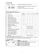
Page 19: ...ved Reserved for future 11 Reserved Reserved for future 12 Hot standby function enable disable Y Y Y Y Y Y 13 Battery voltage adjustment Y Y Y Y Y Y 14 Charger voltage adjustment Y Y Y Y Y Y 15 Invert...

Page 20: ...lected in parameter 2 UPS will transfer to battery mode when input frequency is not within 56 64 Hz If Parameter 2 is ATO the Parameter 2 will show the current frequency Note If the UPS is set to CVCF...

Page 21: ...default value is 54 0Hz 64 0Hz 05 ECO mode enable disable Interface Setting Parameter 2 Enable or disable ECO function You may choose following two options DIS disable ECO function ENA enable ECO fun...

Page 22: ...0Hz 08 Bypass mode setting Interface Setting After it shows 08 in parameter 1 please press Enter key first Then you have the following options to choose in parameter 1 OP Bypass allowed When selected...

Page 23: ...nd it will restart after AC recovery even without battery connected NO Hot standby function is disabled The UPS is running at normal mode and can t restart without battery 13 Battery voltage adjustmen...

Page 24: ...battery specifications 15 Inverter voltage adjustment Interface Setting After it shows 15 in parameter 1 please press Enter key first Then you may choose Ad or SU to adjust inverter voltage in parame...

Page 25: ...assigned numbers may be changed dynamically in the operation Operating mode status AC mode Description When the input voltage is within acceptable range UPS will provide pure and stable AC power to ou...

Page 26: ...mode LCD display Battery mode Description When the input voltage is beyond the acceptable range or power failure UPS will backup power from battery and alarm will beep every 4 seconds LCD display Bypa...

Page 27: ...art failure 01 None Battery SCR short circuited 21 None Bus over 02 None Inverter relay short circuited 24 None Bus under 03 None Charger short circuited 2a None Bus unbalance 04 None Can communicatio...

Page 28: ...ry second Battery unconnected Beeping every second 3 11 Warning Code Warning code Warning event Warning code Warning event 01 Battery unconnected 10 L1 IP fuse broken 07 Over charge 21 Line situations...

Page 29: ...move excess loads from UPS output first Then shut down the UPS and restart it Fault code is shown as 43 The icon lights on LCD display and alarm beeps continuously UPS is overload too long and becomes...

Page 30: ...required precautionary measures may replace batteries and supervise operations Unauthorized persons must be kept well away from the batteries Verify that no voltage between the battery terminals and...

Page 31: ...on applications 12 V 9 Ah Depending on applications Numbers 16 16 20 16 16 20 Recharge Time 7 hours recover to 90 capacity According to external battery pack 9 hours recover to 90 capacity According t...

Reviews: