background image

User manual - Eole T5 + HV460 

202005-418-ENG

P12

4. USE OF THE MACHINE (continued) 

4.3. SPRAY SETTING

To increase or decrease the product flow-rate, use the wheel (E) at the back of the spray-gun:
 

- screw to decrease the flow-rate


- unscrew to increase the flow-rate

To increase or decrease the jet width, use the ring (A):
 

- tighten to obtain a wider jet


- unscrew to obtain a more narrow jet

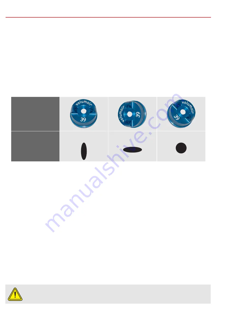
To obtain differents jets, direct the diffuser head as indicated below:

Head position

Spray render

Vertical flat spray

Horizontal flat spray

Round spray

4.4. SETTING UP OF THE EXTENSION POLE

•  The extension pole takes the place of the diffuser head and the jet nozzle.
•  Dismantle the ring (A).
•  Dismantle the jet nozzle (F2).
•  Mount the 1,5 mm needle.
• 

Be sure the joint is well placed.

• 

Mount the extension pole with the ring (A).

•  Block the ring.

4.5. CHANGE OF THE ATOMIZATION KIT

•  Remove the ring (A) and the diffuser head (F1).
• 

Unscrew the setting wheel (E) and remove the spring.

•  Press the trigger, the needle (F3) comes out easily from its housing.
• 

Unscrew the jet nozzle using the key delivered with the spray-gun.

• 

Reassemble the new nozzle jet and screw properly to avoid leaks.

• 

Reassemble the spray-gun in the reverse order of the disassembly, with the new diffuser head.

Changing of the atomization kit, verify that the jet nozzle and the needle have the same 
diameter.

Summary of Contents for Eole T5 + HV460

Page 1: ...nue Olivier Perroy 13790 ROUSSET T l 33 0 4 42 29 08 96 Fax 33 0 4 42 53 44 36 SAS au capital de 400 000 RCS Aix en Provence B 394 961 510 NAF 2892 Z Intracom FR 54 394 961 510 Eole T5 HV460 User manu...

Page 2: ...y 13790 ROUSSET T l 33 0 4 42 29 08 96 Fax 33 0 4 42 53 44 36 SUMMARY 1 USER MANUAL p 3 1 1 Importance of the manual p 3 1 2 Receivers of the manual p 3 2 WARNING p 4 2 1 Safety p 4 2 2 Electric conne...

Page 3: ...by the non compliance of the safety standards and rules This manual must be kept near the machine within reach of the user and held in good condition until the final destruction of the machine In cas...

Page 4: ...a water jet or flammable liquid on the machine Never direct an air jet or product jet on a person or an animal Do not touch warm surfaces of the equipment Always wear adequate body protections glasses...

Page 5: ...hine Take away every not qualified person from the working area of the machine as well as children and animals In case of installation of the machine on scaffolding or a plan above ground level attach...

Page 6: ...t entirely otherwise the equipment can be damaged The section must be proportional to the length of the cord 2 3 END OF LIFE OF THE PRODUCT At its end of life the machine must not be eliminated with t...

Page 7: ...olvent phase 3 2 TECHNICAL CHARACTERISTICS TURBINE Stages 5 Pressure 0 67 bar Air flow rate adjustment yes Power 1700 W Electrical supply 230 V 16 A 50 60 Hz Hose length 7 5 m Dimensions l x w x h 37...

Page 8: ...YOUR MACHINE continued 3 3 IDENTIFICATION OF THE SPRAY GUN COMPONENTS A Nozzle ring B 1 litre bowl C Trigger D Air inlet coupling E Product flow rate adjustment thumbwheel F Atomization kit F1 Diffuse...

Page 9: ...T5 HV460 P9 3 YOUR MACHINE continued 3 4 IDENTIFICATION OF THE TURBINE COMPONENTS H Ventilation filter Bowl filling support I Air outlet coupling J Starting switch K Potentiometer L Thermal circuit b...

Page 10: ...ommendations for use dilution handling etc The product must always be diluted before filling the bowl maximum concentration of pure product 5 Never spray pure products Once the work is finished rinse...

Page 11: ...nd one During utlization use the potentiometer K to increase or decrease the air flow rate into the turbine So that the paint is at the ideal viscosity use the viscosimeter delivered with the turbine...

Page 12: ...POLE The extension pole takes the place of the diffuser head and the jet nozzle Dismantle the ring A Dismantle the jet nozzle F2 Mount the 1 5 mm needle Be sure the joint is well placed Mount the exte...

Page 13: ...a very fluid oil Grease with a consistent grease every thread pitch the front side of the needle nozzle the 2 springs and the centring nut which slides into the back plug Verify and tighten the nut g...

Page 14: ...LE the R 233 73 article of the Labour Code THE DIRECTIVES Machines 2006 42 CE Low voltage 2014 35 UE CEM 2014 30 UE ROHS 2011 65 UE Noise emissions 2005 88 CE AND WITH THE STANDARDS NF EN ISO 12100 NF...

Page 15: ...were totally or partially dismantled Defective equipment will be removed by us Any shipment of equipment by the customer will be at its own expense The guarantee will be subject to the presentation o...

Page 16: ...venue Olivier Perroy 13790 ROUSSET T l 33 0 4 42 29 08 96 Fax 33 0 4 42 53 44 36 SAS au capital de 400 000 RCS Aix en Provence B 394 961 510 NAF 2892 Z Intracom FR 54 394 961 510 User manual Eole T5 H...

Reviews: