background image

This kit contains:

Part  

Quantity  Item in fig.

Lanyard switch 

1

Cable (3889798) 

2

Strip clamp (3889798) 

-

Installation instructions 

-

General

The lanyard switch is connected to the helmsman 

via the cord, if the helmsman falls over or is thrown 

overboard, the lanyard switch is tripped by the cord. 

The engine is then stopped immediately.

Note!

 Position the lanyard switch so that natu-

ral movements can be made without tripping the 

switch. Also ensure that the lanyard switch cord 

cannot become entangled in the throttle lever or 

wheel, since this could cause unintentional tripping 

of the lanyard switch.

Installation


IMPORTANT!

 If the helm ignition key is in the 

passive, locked position (childrens lock), the 

lanyard switch will not function.

1. Turn off the main power breaker from the battery.
2. Drill a hole with Ø16 mm (0.63”). 

 IMPORTANT!

 The panel on which the la-

nyard switch is to be mounted may not be 

thicker than 14 mm (0.55”). 

Depending on the thickness of the panel, use either 

one or both of the plastic nuts (A) to mount the lan-

yard switch.

NOTE! 

To simplify assembly, it is easier to perform 

steps 3 and 4 before the lanyard switch is finally 

mounted on the panel and the plastic nuts are tigh-

tened.

3.  

Gas-EVC, EGC

. Connect the two flat pins on 

the cable supplied (2) to the terminal marked 
NC (normally closed) on the lanyard switch (1); 
see figure 1.


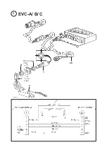
EVC-A, B, C

. Connect the cable (2b) to the 

pin on the lanyard switch (1) as shown in the 
circuit diagram; refer to figure 2. The cable (2b) 
is ordered separately.


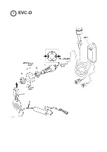
EVC-D.

 Connect the two flat pins marked “TO 

LANYARD” from the AKI unit to the terminal 
marked NC (normally closed) on the lanyard 
switch (1). See figure 3. 
 

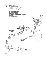
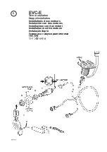
 EVC-E. 

Connect the two flat pins marked “TO 

LANYARD” from cable to the terminal marked 
NC (normally closed) on the lanyard switch (1). 
See figure 4 and 5. 

4. Only applies to Gas EVC, EGC.

Connect the 

blue/red

 cable provided on the re-

ceptacle housing (B) to the ignition switch terminal 

marked I. Fit the supplied 

violet

 cable snap con-

nector (C) onto the 

violet

 cable in the ignition switch 

harness.
5. Mount the lanyard switch onto the panel using the 

plastic nut(s) (A).
6. Turn the main switch to on. The EVC will auto-

configure the lanyard switch.
7. Start the engine and check the function of the la

-

nyard switch by pulling the cord.

 IMPORTANT!

 Check that the lanyard switch 

is functional regularly. The engine shall stop 

immediately when the lanyard switch is  

triggered.

Summary of Contents for 21469024

Page 1: ...e Disyuntor de seguridad LANYARD Kit número 3889798 21469024 Instruzioni di montaggio Interruttore di sicurezza LANYARD Kit numero 3889798 21469024 Monteringsanvisning Säkerhetsbrytare LANYARD Satsnummer 3889798 21469024 Instruções de instalação Interruptor de segurança CABO DE DESLIGAMENTO Kit número 3889798 21469024 Инструкция по установке Aварийный выключатель с тросовым талрепом LANYARD Номер ...

Page 2: ...ecializzato Le istruzioni di montaggio sono state redatte esclusivamente per uso professionale e non sono adatte all uso non professionale La Volvo Penta non si assume alcuna responsabilità per even tuali danni alle cose o alle persone derivanti da trascuratezza nel seguire le istruzioni di montaggio oppure dall esecuzione dei lavori da parte di personale non qualificato VIKTIGT Denna sats med för...

Page 3: ...1 A A 1 C Gas EVC EGC 1 2 B 2 ...

Page 4: ...2 EVC A B C X4 MAX 14 mm 0 55 14 mm 0 55 1 2 A A 1 1 2b 2 ...

Page 5: ...AKI A A 1 3 EVC D 1 2 ...

Page 6: ... E Singel installation Installation mit einem Motor Installation de Singel Instalación con un solo motor Singel installazione Singel installation Instalação simples Установка с одним двигателем 单独安装 シングル取り付け eKey 2 ...

Page 7: ...allation Doppelinstallation Installations deux moteurs Instalación con dos motores Installazione con due motori Installation med två motorer Instalação dupla Установка с двумя двигателями 双机安装 ツイン取り付け 5 1 1 A A eKey 2 ...

Page 8: ...and 4 before the lanyard switch is finally mounted on the panel and the plastic nuts are tigh tened 3 Gas EVC EGC Connect the two flat pins on the cable supplied 2 to the terminal marked NC normally closed on the lanyard switch 1 see figure 1 EVC A B C Connect the cable 2b to the pin on the lanyard switch 1 as shown in the circuit diagram refer to figure 2 The cable 2b is ordered separately EVC D ...

Page 9: ...e Kunststoffmuttern angezogen werden 3 Benzin EVC EGC Die beiden Flachstifte auf der beigefügten Leitung 2 an den Stift mit der Bezeichnung NC normally closed auf dem Si cherheitsschalter 1 anschließen siehe Bild 1 EVC A B C Leitung 2b nach dem Schalt plan an den Stift auf dem Sicherheitsschalter 1 anschließen siehe Bild 2 Die Leitung 2b ist separat zu bestellen EVC D Die beiden Flachstifte mit de...

Page 10: ...rcuit sur le panneau et de serrer la les écrou s en plastique 3 EVC EGC Essence Raccorder les deux coss es plates du câble fourni 2 sur les broches marquées NC normalement ouvert sur le coupe circuit de sécurité 1 voir la fig 1 EVC A B C Raccorder le câble 2b à la bro che sur le coupe circuit de sécurité 1 selon le schéma de câblage voir la fig 2 Le câble 2b se commande séparément EVC D Raccorder ...

Page 11: ...panel y apretar las tuercas 3 Gasolina EVC EGC Conectar las dos clavijas planas en el cable incluido 2 a la clavija mar cada NC normally closed en el disyuntor de seguridad 1 ver figura 1 EVC A B C Acoplar el cable 2b a la clavija en el interruptor de seguridad 1 según el es quema de acoplamiento ver figura 2 El cable 2b se solicita por separado EVC D Conectar las dos clavijas planas mar cadas TO ...

Page 12: ...punti 3 4 prima di fissare definitivamente l in terruttore sul pannello e serrare i dadi di plastica 3 Benzina EVC EGC Collegare i due terminali piatti del cavo allegato 2 allo spinotto mar cato NC normalmente chiuso sull interruttore di sicurezza 1 vedere fig 1 EVC A B C Collegare il cavo 2b al pin sull interruttore di sicurezza 1 come da sche ma elettrico vedere fig 2 Il cavo 2b va ordi nato sep...

Page 13: ...t lämpligt att göra steg 3 4 innan säkerhetsbrytaren slutligen fixeras vid panelen och plastmuttrarna dras åt 3 Gas EVC EGC Anslut de två flatstiften på den bifogade kabeln 2 till stift märkt NC normally closed på säkerhetsbrytaren 1 se bild 1 EVC A B C Anslut kabeln 2b till stift på säk erhetsbrytaren 1 enligt kopplings schema se bild 2 Kabel 2b beställs separat EVC D Anslut de två flatstiften mä...

Page 14: ...amento ser finalmente montado no painel e as porcas plásticas apertadas 3 Gas EVC EGC Conectar os dois pinos planos no cabo fornecido 2 ao terminal marcado NC normalmente fechado no interruptor do cabo de desligamento 1 consultar a figura 1 EVC A B C Conectar o cabo 2b ao pino do interruptor do cabo de desligamento 1 confor me mostrado no diagrama elétrico consultar a figura 2 O cabo 2b é encomend...

Page 15: ...выключатель будет окончательно установлен на панель и будут затянуты пластиковые гайки 3 Бензиновые EVC EGC Вставьте два плоских штырька прилагаемого провода 2 в гнезда NC нормально замкнутые на выключателе с тросовым талрепом 1 см рис 1 EVC A B C Подсоедините трос 2b к контакту на разъединительном выключателе 1 как показано на принципиальной схеме 2 Трос 2b заказывается отдельно EVC D Вставьте дв...

Page 16: ...个或两个塑料螺母 A 安装 推拉式急停开关 注意 若要简化装配 请在最终将推拉式急停开关 安装到面板上并紧固塑料螺母之前先执行步骤3和4 这样会更加简单 3 燃气 EVC EGC 将提供的电缆 2 上的两个 扁平针脚连接到推拉式急停开关 1 上的标记有 NC 常关 的端子 参见图1 EVC A B C 将电缆 2b 连接到推拉式急停开关 1 上的针脚如电路图所示 参见图2 电缆 2b 为单独订购 EVC D 将标记有 至短索 的两个扁平针脚从AKI 单元连接至推拉式急停开关 1 上标记有NC 常 关 的端子 参见图3 EVC E 将标记有 至短索 的两个扁平针脚从电缆连 接至推拉式急停开关 1 上标记有NC 常关 的 端子 参见图4和5 4 仅适用于燃气EVC EGC 将插座壳体 B 上提供的蓝 红色电缆连接至标记有I的 点火开关端子 将提供的紫色电缆瞬动接头 C 安装 到点火开关线束中的...

Page 17: ...と4 を 実行してから 最終的にラニヤードスイッチをパネル に取り付けて プラスチックナットを締め付けます 3 Gas EVC EGC ラニヤードスイッチ 1 の NC 通常閉じ と書かれた端子に 付属ケー ブル 2 のフラットピン 2 本を接続します 図 1 を参照してください EVC A B C 回路図に従って ケーブル 2b をラニヤードスイッチ 1 のピンに接続しま す 図 2 を参照してください ケーブル 2b は別発注になります EVC D ラニヤードスイッチ 1 の NC 通常閉 じ と書かれた端子に AKI ユニットからの フラットピン 2 本 TO LANYARD ラニ ヤードへ と書かれている を 接続しま す 図 3 を参照してください EVC E ラニヤードスイッチ 1 の NC 通常閉じ と書かれた端子に ケーブルからのフラット ピン 2 本 TO LANYARD...

Page 18: ...47700860 03 2013 Tab 6 AB Volvo Penta SE 405 08 Göteborg Sweden www volvopenta com ...

Reviews: