21
49.
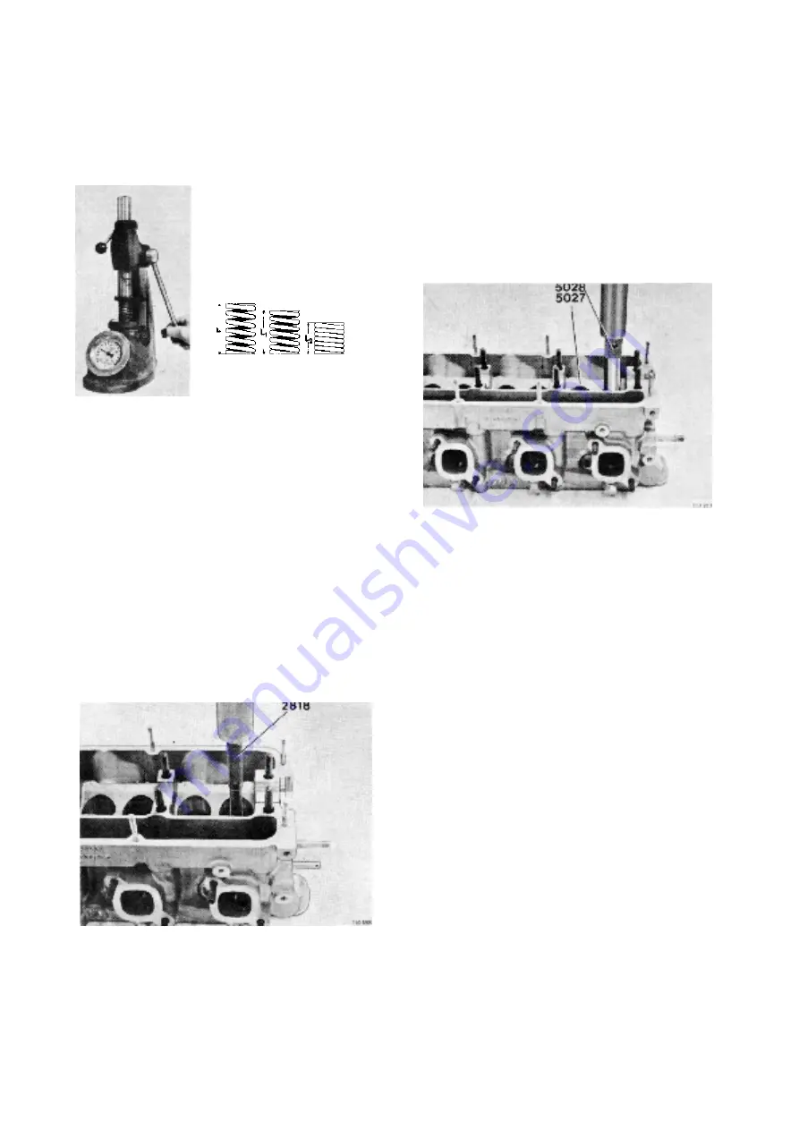
Check the valve springs.
Length unloaded
45 mm (1.77")
Length loaded with 300±20 N
(67.2±4.48 lbf.)
38 mm (1.50")
Length loaded with 760±40 N
(170±8.96 lbf.)
27 mm (1.06")
Changing the valve guides
50.
Press up the valve guides with tool 999 2818.
Heat the cylinder head in 60°C (140°F) water.
51.
Fit the new valve guides. Use tool 999 5027 for
the inlet valves and tool 999 5028 for the exhaust
valves. The cylinder head is to be at room tempe-
rature. The pressing force for fitting the valve gui-
des is to be at least 9000 N (900 kp) (2016 lbf). If
this pressing force is not obtained for the guides
the hole is to be reamed and a suitable oversized
valve guide is to be fitted. Press the guide down
until the tool comes up against the cylinder head.
This gives the guide a height above the valves
spring face around the guide of: 15.5±0.1 mm
(0.610±0.004") for the inlet valve and 18.0±0.1
mm (0.708±0.004") for the exhaust valve.
Summary of Contents for AQ125A
Page 1: ...Workshop Manual Engine Unit AQ125A B AQ145A B C 2 0 ...
Page 2: ......
Page 74: ...7739856 8 English 11 1998 ...


