40
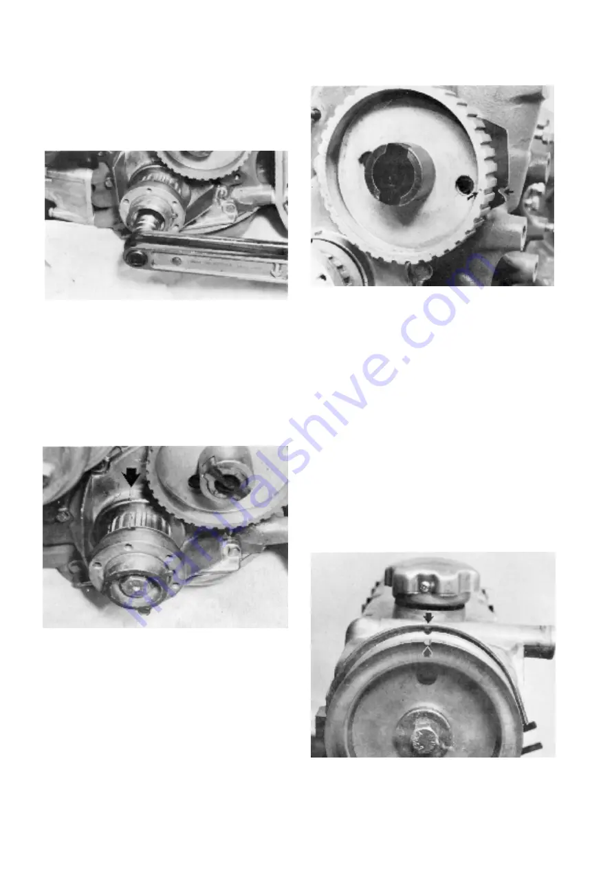
123. Paint mineral grease or similar lubricant in the
hub on the crankshaft’s pulley. Position the guide
plate (turn the bend towards the seal) and fit the
pulley on the crankshaft. Then refit the outer plate
and the carrier and fit the screws. The tightening
torque is 165 Nm (16.5 kpm) (122 lbf. ft.). Use a
suitable counterforce.
124. Turn the crankshaft into position after marking.
Nick on the inner guide plate.
125. Turn the intermediate shaft into position after
marking.
126. Place the valve cover in position without the gas-
ket. Check that the camshaft’s pulley’s marking
agrees with the marking on the valve cover.
Then check that the timing belt is in good condi-
tion. NOTE! Oil or grease must not be used on the
belt. Coloured marks (stripes) are on the belt so
that the adjustment can be checked. Line up the
mark with two stripes against the crankshaft
pulley’s marking and then the marking with one
stripe against the intermediate shaft pulley’s
marking and finally the marking with one stripe
against the camshaft pulley’s marking.
Summary of Contents for AQ125A
Page 1: ...Workshop Manual Engine Unit AQ125A B AQ145A B C 2 0 ...
Page 2: ......
Page 74: ...7739856 8 English 11 1998 ...


