13
On the TAMD60 engines, small quantities required for
topping-up can be added to the expansion tank, but other-
wise coolant should always be filled directly into the heat
exchanger through the hole for the hexagon plug, until the
engine is completely full and vented. Then close the ven-
ting cock at the turbo and screw the hexagon plug on the
heat exchanger. Thereafter, fill the expansion tank at the
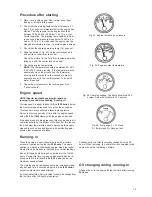
side of the engine (1, fig. 11) with approx. 3 litres (0.66 Imp.
galls = 0.80 US galls) and replace the cap.
1.
If the engine is connected to a cabin heater, this must
also be vented before the cap on the expansion tank or
the plug on the heat exchanger are fitted. Otherwise
the engine may be damaged due to insufficient
cooling.
Finally, fill the separate expansion tank, if fitted, to
slightly above the MIN. level.
If the engine should run abnormally hot, carefully
vent the cooling system and top up with water.
2.
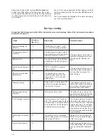
Lubricating oil level, engine. Check that the level is
between the marks on the dipstick. It must never be
permitted to fall below the lower mark.
(Check that the cock under the oil scavenging pump,
on the 70C-engine, is closed, see page 24.)
3.
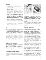
Oil level, reverse gear. The level should reach the
mark (alternatively, it should lie between the two
marks) on the dipstick. Repeat the check for Twin Disc
reverse gears whilst idling with the control in the neu-
tral position, since this indicates the true level for this
type of reverse gear.
The oil level in the Borg Warner and SCG reverse
gears should be checked when the engine is not
running. The oil level will lie above the ”max.” mark
when the engine has been stationary long enough for
the oil to run down from the cooler and passages. To
obtain a true level reading the check should be made
immediately after the engine has been stopped.
4.
Check that the seawater cocks on the engine are
closed. See the figures on page 18.
5.
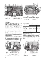
Open the bottom valve and the trickle-feed cock to the
bilge pump, if fitted. (Fig. 18).
6.
Fuel. Check that there is sufficient fuel in the tanks and
open the fuel cocks.
7.
Switch on the master switches. They should be on
when the engine is running.
NOTE! Switching off and on must never be carried out
while the engine is running, since this can damage the
charging regulator.
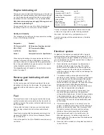
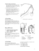
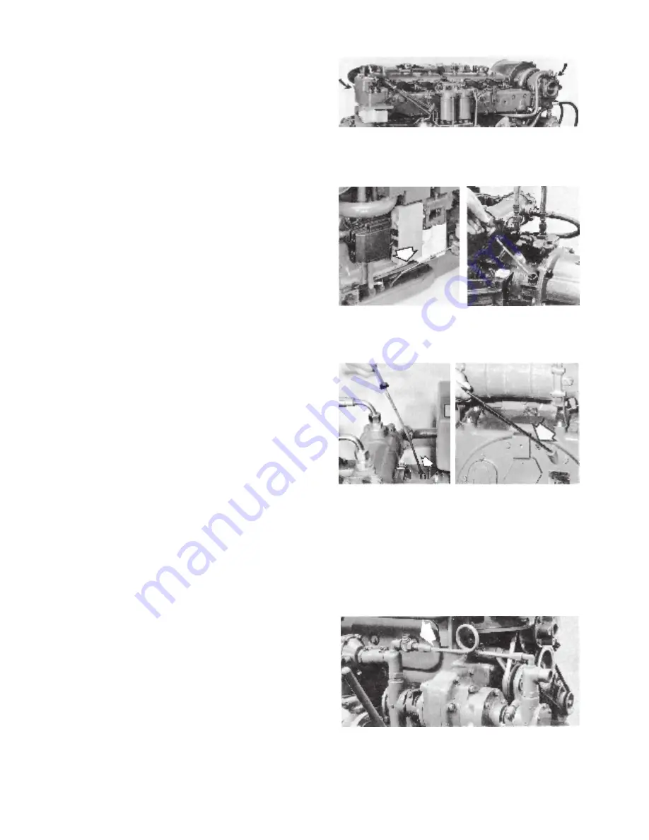
Fig. 13. Vent the cooling system. (The picture shows a 70C
engine.)
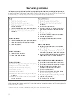
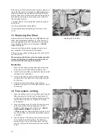
Fig. 14. Oil level, all engines
(the picture shows a 70-type
engine).
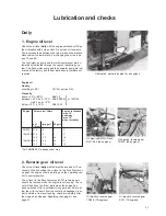
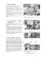
Fig. 15. Check the oil level
in reverse gear BW and
V-drive BW 10-05.
Fig. 16. Check the oil level
in the reverse gear TD.
Fig. 17. Check the oil level in
reverse gear SCG.
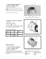
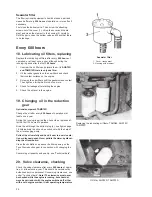
Fig. 18. Cock on trickle-feed line to bilge pump, if fitted. The
scribed line should be in line with the pipe when the cock is
open.


