88
11
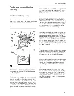
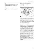
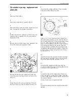
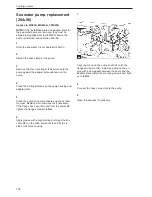
Install the diaphragm in position above the bottom
pump half with the connecting arm fin upwards to-
wards the slit in the control arm. Ensure that the
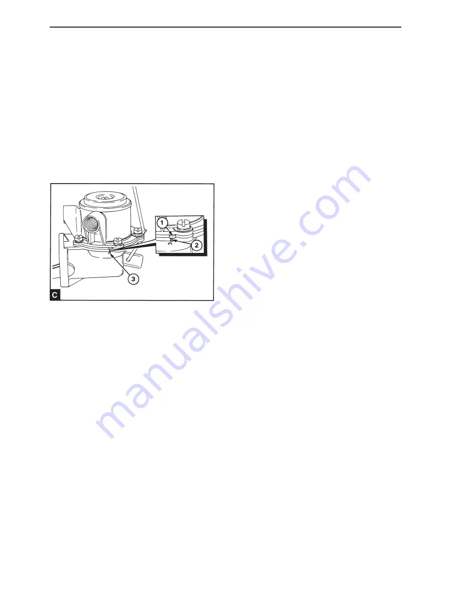
small bulge in the edge of the diaphragm (19A.04/
C1) is at a 90° angle to the similar bulge on the
pump housing (19A.04/C2). Press the diaphragm
lightly down until the notch in the connecting rod is
in the slit in the control arm. Turn the diaphragm 90°
to ensure that the bulge on the edge of the dia-
phragm corresponds with the bulge on the pump
housing. This ensures that the connecting rod goes
into and remains in the slit in the control arm.
12
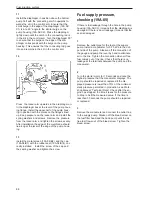
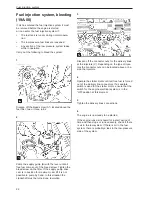
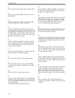
Press the rocker arm upwards in the diaphragm un-
til the diaphragm lies at the level of the pump hous-
ing flange. Install the upper half of the pump hous-
ing in position with the marks on the flanges lined
up. Keep pressure on the rocker arm and install the
spring washers and screws. Remove the pressure
from the rocker arm and tighten the screws evenly.
After installation the edge of the membrane should
lie along at the level of the edge of the pump hous-
ing.
13
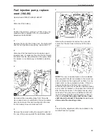
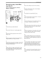
Install the metal screen (19A.04/B2) and the cap
(19A.04/B1) with the rubber seal (19A.04/B14) cor-
rectly installed. Install the screw of the cap and
the sealing washer and tighten the screw.
Fuel supply pressure,
checking (19A-05)
If there is fuel leakage through the hole in the pump
housing (19A.04/C3), it means that the diaphragm is
damaged. If there is an oil leakage it means that the
seal is damaged.
1
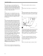
Remove the outlet pipe for the fuel at the supply
pump. Install a manometer for 0-70 kPa to the out-
put side of the pump. Slacken off the connection of
the gauge and pump the lever by hand to eliminate
air in the line. Tighten the connection when air free
fuel comes out of the line. Check that there is no
leakage at the terminals between the pump and the
manometer.
2
Turn the starter motor for 10 seconds and note the
highest pressure that the manometer displays. The
pump should be repaired or replaced if the dis-
played pressure is lower than 75% of the minimum
static pressure permitted in production, see Work-
shop Manual “Technical Data”. Check after the en-
gine has stopped, the time it takes for the pressure
to drop to half the measured value. If the time is
less than 30 seconds the pump should be repaired
or replaced.
3
Remove the manometer and connect the outlet line
to the supply pump. Slacken off the bleed screw on
the fuel filter head and the hand pump until the air
free fuel flows out of the bleed screw. Tighten the
bleed screw.
Fuel injection system
Summary of Contents for MD22
Page 1: ...Engine repair MD22 TMD22 TAMD22 Workshop Manual 2 0 A ...
Page 2: ......
Page 129: ...127 Notes ...
Page 130: ...128 Notes ...
Page 132: ...7738684 5 English 04 1999 ...

