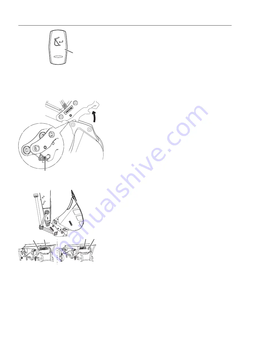
4 Open the attachment quick coupler as follows:
Press down and hold the upper end of the spring returned
quick coupler confirmation switch (3) on the left instrument
panel for 1 second.
A red quick coupler symbol and a warning message for
unlocked quick coupler will appear in the IC (Instrument
Cluster).
5 Ensure that the rear locking hook (B) is unlocked before
hooking onto the bucket pin. Otherwise the bucket pin could
not be engaged properly.
6 Curl the attachment quick coupler and hook it onto the bucket
pin.
7 Slowly curl in the attachment quick coupler towards the
bucket.
8 Press the lower end of the attachment quick coupler switch (2)
to close the quick coupler.
A yellow quick coupler symbol and a check message for quick
coupler locking confirmation will appear in the IC (Instrument
Cluster) and the buzzer sound will continue.
N
N
O
O
T
T
E
E
!
Visually check that the front pin lock is fully engaged.
9 Lift and curl in the bucket fully towards the dipper arm and hold
it there for approximately 5 seconds to ensure the attachment
quick coupler has fully locked on to the bucket.
A visual indicator that the bucket is locked in the universal
quick coupler is the position of the locking hook (E) on the
bucket pin (D), see illustration.
10 When the attachment is correctly locked in the attachment
quick coupler, this has to be confirmed by pressing the upper
end of the attachment quick coupler confirmation switch (3) for
1 second.
A yellow quick coupler symbol and a check message for quick
coupler locking confirmation will disappear in the IC
(Instrument Cluster) and the buzzer sound will stop.
11 Test if the attachment quick coupler is securely fastened with
the following procedure:
V1148413
3
3. Attachment quick coupler confirmation switch
(left instrument panel)
V1152058
C
C - Front pin lock (FPL)
E
D
E
D
(1)
(2)
V1152057
D. Bucket pin
E. Locking hook
(1) Locking hook fully extended, locked position
(2) Locking hook fully retracted, unlocked position
21
1
8
8
Op
p
e
e
r
r
a
a
t
t
i
i
n
n
g
g
te
e
c
c
hn
n
i
i
q
q
u
u
e
e
s
s
At
t
t
t
a
a
c
c
hm
m
e
e
n
n
t
t
s
s
, con
n
n
n
e
e
c
c
ti
i
n
n
g
g
an
n
d
d
di
i
s
s
con
n
n
n
e
e
c
c
ti
i
n
n
g
g
Summary of Contents for 322001
Page 7: ...5 5 ...
Page 146: ...Right mirrors 1 14 44 4 Op pe er ra at ti in ng g in ns str ru uc cti io on ns s ...
Page 172: ...1 170 Operating instructions Exhaust aftertreatment system ...
Page 357: ...S Specifications Dimensions 355 ...
Page 410: ......
Page 413: ......
Page 414: ...4 412 Alphabetical index Ref No 20052711 C Volvo Eskilstuna English ...


