Group
28
Ig
n
i
t
i
on systems
Design and func
t
ion -
Engine
(oad in
format
io
n
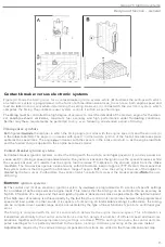
Engine load information
Intake manifold vacuum
The control unit
is
supplied with
information on
engine
load
through the
line (
1
)
from
th
e
intake manifold.
load
information
th
rough vacuum line
When the
engine load is low.
the
throttle
is
only panially
open
and the vacuum
in
the
manifold is high
la
pprox
.
60
kPa
).
As
the
engine
lo
ad
increases.
the throttle
opens
furt
her and
t
he vacuum in the manifold gradually
falls
.
The
ignition
s
yst
em may
re
ceive and process
the
load
from
in
t
ake
mani
f
old
by
one of
three basic methods
in order
t
o adjust/compu
t
e
the t
iming se
tt
in
g.
Vacuum
advance unit
A
.
On
the
TZ
-
28H
system, the vacuum
line
is connected
a vacuum advance unit
(3)
on
t
he distribu
t
or. The unit
h
ouses
a diaphragm,
one side of
which
is
open
to
vacuum
in
the manifold and
other
to
atmosphere.
A
s
the
vacuum increases
(a
t
low engine
load
with
a partially-open
thr
o
ttle
),
distributor plate is ro
t
ated
to
advan
ce
t
he
t
iming.
El
ectrical
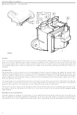
vacuum converter
B
. The vacuum line on
the
Renix-F
sys
tem
is connected
to a vacuum
con"erter integral
with the
con
trol
unit.
A
l-
though
vacuum converter
is
designed specifically for a particular system,
the
principle
o
f
operation
is
the
same in
cases.
The
vacuum
is
applied
t
o
one side
of
a spring-loaded diaphragm
(
4
).
the
other
side
of
which
car-
ries
iron core
(5)
inside a
coil (6)
.
The coil
connected
to an
oscilla
tor
ci
r
cui
t
in
the
con
tro
l
unit,
the
fre-
quency
in
wh
ich
varies
w
ith
the position
o
f the
core
and. as a
result. is
proportional
to
engine
load.
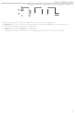
Electronic
pressure
switch
C
.
On
the
EZ
-1
18K
system.
th
e vacuum line
IS
connec
t
ed
to
pressu
r
e switch
(7)
insi
de the
control uni
t
.
The
device
consists
of
a
diaphragm
.
a magnet and a
semiconduc
tor
element. The diaph
rag
m is actuated by
the vacuum
on
one
side.
while
the
other
a
tt
ached to the magnet.
The po
si
t
ion
of
th
e
magne
t
influences
the
curren
t
flow
in
the
semiconducto
r
and. as a
re
sul
t
.
the
value of
t
he
i
nduced Hall
voltage.
Thus. the voltage
is
proportional to
th
e
posi
t
ion o
f
the
magnet and, by extensio
n
.
t
o
t
he engine load
.
The load sig
-
nal
received
by
the
conve
rt
er in
the
con
tr
ol
unit
and used
to
compute
the
t
iming.
25


