Group 28 Ignition systems
Des
ign
and
funct
io
n
System descriptions
III
8
EZ-116K
B 234 F
,
B204E and B230F
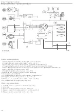
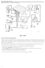
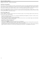
The
control
un
i
t
(
1
)
computes
the
optimum
timing
on
the
bas
is
of information
from the
arious
sensors
.
Th
e
power
stage (2)
makes
and
breaks the
cu
rrent in the primary winding
of
the ignition
co
il
(3)
response
t
o
ignition pulses
from
th
e con
trol
unit
.
The high
-
tension
current
thereby
induced in
the
secondary is
supplied
to
the appropriate spark
plug
(5)
by
th
e
distributor
(
4).
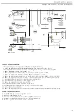
The
con
tro
l
unit
also supplies signals
to the diagnostic
uni
t
used
f
or
fault
tra
cing
and monitoring purposes.
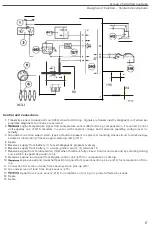
The ignition
setting computed by
the
control
un
i
t
is
based
on
t
he
follow
i
ng
i
nformation
:
-
Eng
ine
speed and crankshaft position are
indic
ated
by
the
speed/position pick-up
(6).
-
Eng
i
ne
kno
c
k
is
by
the knock
sensor
(
8
).
The fue
l
system
(
lH
-
2
.
4
)
control unit
(
9
)
transm
i
ts
eng
i
ne
load s
i
gnals from
the air mass meter
.
-
Engine temperature
indi
c
ated
by the
temperature sensor
-
Closure
of
the throttle
ind
i
cated
by the
throttle switch
.
•
The control unit can vary the
t
i
ming
from
approx
.
55
·
before TOC t
o
after
TOC
.
58

