6
Instruments and controls
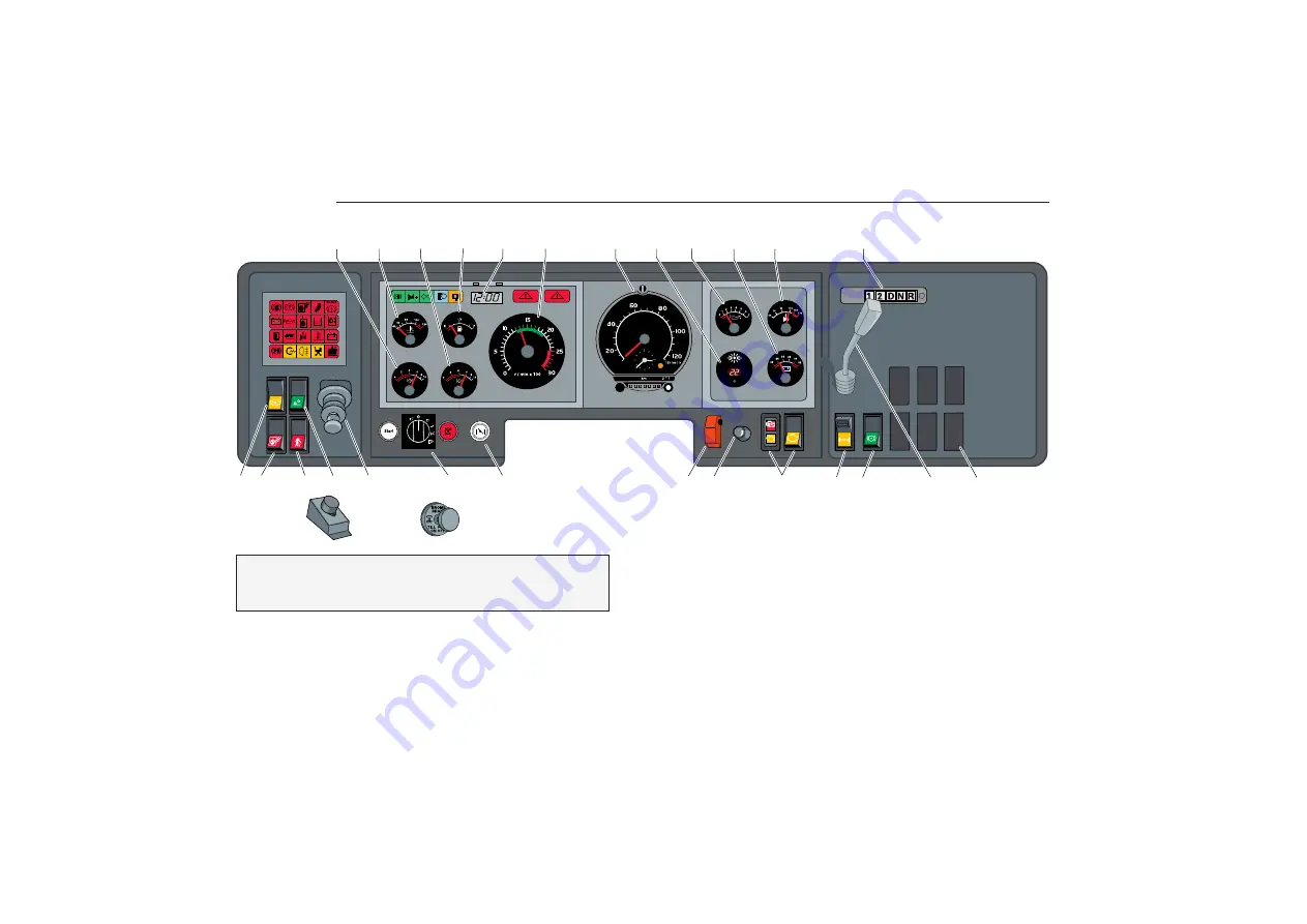
Dashboard
The illustrations show the most common switch loca-
tions, but there can be variations. Symbols and explana-
tions of functions are, however, always accurate.
6. Engine speed .......................................................... 16
7. Tachograph/speedometer ...................................... 20
8. Temperature, ext./int. .............................................. 31
8. alt. compressed air (articulated bus) ...................... 24
9. Lubricant pressure, engine ..................................... 17
10. Voltmeter ................................................................. 15
11. Oil temperature, automatic gearbox ....................... 19
or
11. Turbo pressure ........................................................ 16
12. Gear selector, automatic gearbox .......................... 42
1
2
3
4
5
6
7
8
9
10
11
12
13 14 15 16
17
20
21
22
23
24
25 26
27
28
18
19
page
1. Compressed air, front circuit .................................... 24
2. Coolant temperature ............................................... 18
3. Compressed air, rear circuit ................................... 24
4. Fuel level ................................................................. 16
5. Clock and tripmeter ................................................. 31
Left hand drive
bus
Summary of Contents for B10M
Page 1: ...Driver s Manual...
Page 6: ...4 Pay attention to warning and indicator lights Their purpose is to warn of danger...
Page 131: ...129 TechnicalData Type plates 130 Specifications Data 132...
Page 142: ...140 Notes...
Page 143: ...141 Notes...
Page 144: ...142 Notes...
Page 145: ...143 Notes...
Page 146: ...144 Notes...
Page 147: ...3 Notes...


