82
If anything happens
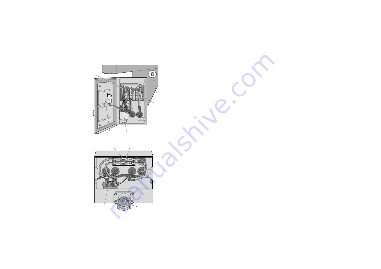
Fuses and relay in junction box in front of
core assembly
Fuse
Amperage
Circuit
33
150A
Starting heater
37
200A
Electric retarder
46
10A
Reserve supply EDC
Relay
Circuit
312
Starting heater
No.
Description
X
Mechanical engine shut-down
Fuses and relays in electrical distribution box
in front end of battery box
Applies to buses with original battery box (located under the
driver’s position).
Fuse
Amperage
Circuit
34
80A
Supply to electrical distribution box
after battery master switch (”+30”)
35
80A
Supply to electrical distribution box
before battery master switch (”+”)
Relay
Circuit
342A
Electric battery master switch
No.
Description
85
Rapid charge socket
ENGINE
STOP
46
37
33
312
X
342A
85
34
35
Summary of Contents for B10M
Page 1: ...Driver s Manual...
Page 6: ...4 Pay attention to warning and indicator lights Their purpose is to warn of danger...
Page 131: ...129 TechnicalData Type plates 130 Specifications Data 132...
Page 142: ...140 Notes...
Page 143: ...141 Notes...
Page 144: ...142 Notes...
Page 145: ...143 Notes...
Page 146: ...144 Notes...
Page 147: ...3 Notes...

