92
Sweden
Ver.
24 VOLT
826
1234567
826
1234567
If anything happens
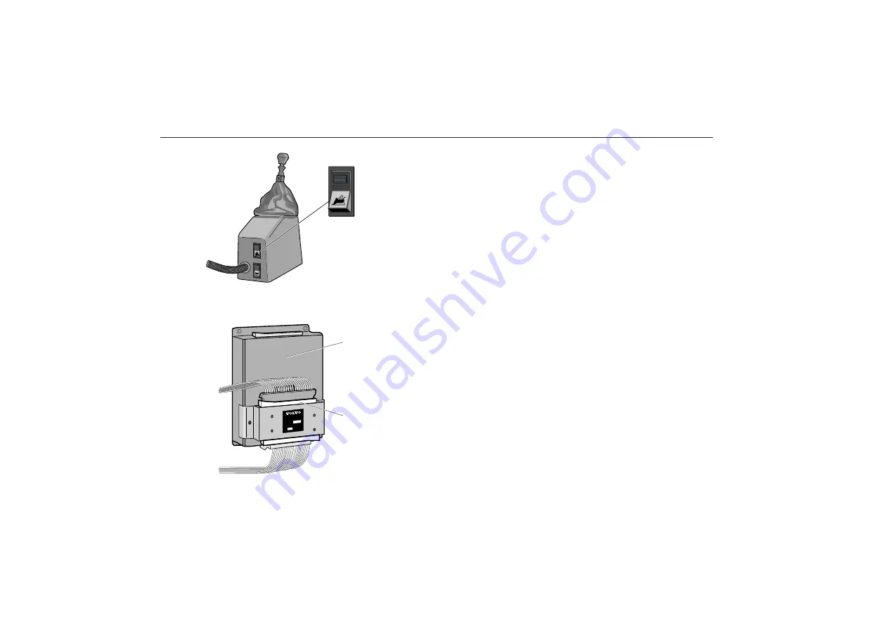
Integral emergency operation system
The first emergency operation system to be engaged is the
one that is integrated with the ordinary control unit. It can be
engaged with the emergency operation switch. The engine
must be running and the bus must be stationary when en-
gaging. Emergency operation can not be disengaged with
the engine running and if it is still required, it must be re-
engaged each time the engine is started. The diagnostic
lamp will flash when this emergency operation system is
active.
Gear positions 1–5 and reverse should now work, gear po-
sitions 6 and 7 and the +gear are blocked. Shifting is per-
formed slower than normal.
Separate emergency operation board
If it is still impossible to change gear, the emergency opera-
tion board can be engaged as follows:
–
Depress the catch on the upper connector on the control
unit. Lift off the connector starting at the end where the
catch is.
–
Plug this connector to the upper terminal block on the
emergency operation board.
–
Unplug the lower connector from the control unit. Con-
nect it to the lower terminal block on the emergency op-
erationboard.
It should now be possible to change gear with limited shift-
ing functions, meaning gear 1–4 and reverse. Safety func-
tion present in the ordinary control unit are
not
included in
the emergency operation board. This means that special
attention must be paid to engine speed when changing
gear.
Emergency
operation
switch
EGS control
unit
Emergency
operation
board
Summary of Contents for B10M
Page 1: ...Driver s Manual...
Page 6: ...4 Pay attention to warning and indicator lights Their purpose is to warn of danger...
Page 131: ...129 TechnicalData Type plates 130 Specifications Data 132...
Page 142: ...140 Notes...
Page 143: ...141 Notes...
Page 144: ...142 Notes...
Page 145: ...143 Notes...
Page 146: ...144 Notes...
Page 147: ...3 Notes...


