94
The suspension system is powered via fuse no. 15.
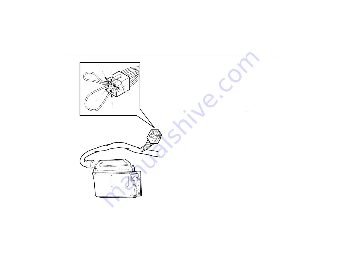
Fault tracing is normally carried out with a computer (PC). A
simpler form of diagnosis can be performed with a few cable
ends only. Locate the 9-pin connector marked ”DIA” hang-
ing on the cable harness from the suspension control unit.
For safety reasons, the suspension is connected so that it is
activated (and controlled) only once the engine has been
started. (Actually: when the alternator is charging.) In order
to retrieve fault codes from the warning and diagnostic
lamp, the engine must be running or pins ”1” and ”2” in the
connector coupled together with a cable end. Temporarily
couple together pins ”4” and ”8”. The lamp on the dash-
board will start to flash any fault codes (see table below)
when this coupling is broken. Fault codes can be cleared by
jumping pins ”4” and ”8” as above and placing another ca-
ble between pins ”3” and ”8”.
If anything happens
BOSCH
3
1
4
8
2
Continued from previous page
Summary of Contents for B10M
Page 1: ...Driver s Manual...
Page 6: ...4 Pay attention to warning and indicator lights Their purpose is to warn of danger...
Page 131: ...129 TechnicalData Type plates 130 Specifications Data 132...
Page 142: ...140 Notes...
Page 143: ...141 Notes...
Page 144: ...142 Notes...
Page 145: ...143 Notes...
Page 146: ...144 Notes...
Page 147: ...3 Notes...


