background image

Sound Absorption

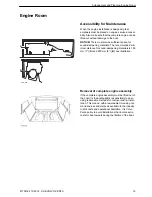
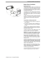
The drive assembly must be installed so that noise and
vibrations are minimized. The noise that occurs is party
airborne noise and partly structural noise (vibrations).

Structural noise

Engine vibrations are transferred to the hull via the
engine mounts and engine bed. Other transfer routes
are through the transmission and propeller system,
exhaust pipes, coolant pipes, fuel pipes and electrical
and control cables.

Propeller pressure waves are transmitted through the
water to the hull. Propeller drive pulses are transferred
to the hull via support brackets, bearings and seals.

Airborne noise

This section concerns airborne noise from the engine
compartment. The most important method of reducing
airborne noise from the engine compartment is to seal
it properly. Further noise reductions can be achieved
by laying sound insulation material and by designing
noise baffles in the air inlets.

The engine installation must be noise insulated to pro-
vide as low a noise level as possible. Build noise baf-
fles into the engine compartment. There are different
types of noise baffles to choose from. The illustration
shows a type that also provides drainage.

It is important to ensure that the insulation material is
sufficiently thick.

The greatest possible care must be taken to screen the
noise source as much as possible. Screen off the entire
bulkhead down to the hull, but leave a little gap so that
bilge water does not force its way into the insulation
material.

Cracks and openings etc. must be carefully sealed with
insulation material. In cases where the engine is instal-
led beneath the deck, all bulkheads and decks must be
insulated.

1

P0004735

Engine compartment noise baffles


Arrangement and Planning, Sound Absorption

30

47704162 10-2014  © AB VOLVO PENTA

Summary of Contents for IPS650

Page 1: ...IPS 2 IPS650 IPS800 IPS950 Installation 1 1 E ...

Page 2: ......

Page 3: ...nta IPS 51 Fiberglass Hull Constructions 51 Aluminium Hull Constructions 81 Engine Foundation 82 Propulsion Unit Installation 87 Engine Installation 92 Extension Shaft 96 Exhaust System 98 Cooling System 100 Fuel System 111 General 111 Fuel Tanks 112 Piping 116 Fuel pressure 118 Lubrication System 119 Electrical System 120 Batteries 121 Alternator 130 Voltage Supply 131 Connection 132 Fire Extingu...

Page 4: ...at exhaust fumes are toxic and danger ous to inhale Use an exhaust extractor to lead exhaust fumes away from the exhaust pipe and crank case ventilator when the engine is run in a confined space Always wear protective goggles if there is a risk of splinters sparks and splashes from acid or other chemicals Eyes are extremely sensitive and injury may result in loss of sight Avoid getting oil on the ...

Page 5: ...en the engine is hot Steam or hot coolant may be ejected when system pressure is released Open the filler cap slowly and release the system pressure carefully freshwater cooled engines Hot coolant may spray out if the filler cap or drain tap is opened or if a plug or coolant pipe is removed from a hot engine Hot oil can cause burns Avoid getting oil on the skin Be sure to release the pressure from...

Page 6: ...e hoist and the other to make sure no components catch or are damaged The components in the electrical system ignition system gasoline engines and fuel system on Volvo Penta products are designed and manufactured to minimize the risk of fire and explosion Do not run engines in areas where there are explosive materials Always use fuels recommended by Volvo Penta Refer to the Operator s Manual Poor ...

Page 7: ...change installa tion methods will be communicated via service bulle tins Removal of complete engine assembly In the event of a requirement to remove the entire engine assembly from the vessel it is the responsi bility of the boat builder to arrange reasonable means for removal and re installation Reasonable means that the engine assembly can be lifted in and out within a moderate amount of time us...

Page 8: ...tailed descrip tions of safety requirements From June 16 1998 all leisure craft and certain asso ciated equipment that is marketed and used within the EU must be provided with a CE label confirming ful fillment of safety requirements established by the European Parliament and European commission in the Recreational Craft Directive These normative standards are reflected in the standards establishe...

Page 9: ...es Nm lbf ft 0 738 lbf ft Nm 1 356 Pressures Bar psi 14 5038 psi Bar 0 06895 MPa psi 145 038 psi MPa 0 006895 Pa mm Wg 0 102 mm Wg Pa 9 807 Pa in Wg 0 004 in Wg Pa 249 098 kPa in Wg 4 0 in Wg kPa 0 24908 mWg in Wg 39 37 in Wg mWg 0 0254 Energy kJ kWh BTU hph 0 697 BTU hph kJ kWh 1 435 Labor kJ kg BTU lb 0 430 BTU lb kJ kg 2 326 MJ kg BTU lb 430 BTU lb MJ kg 0 00233 kJ kg kcal kg 0 239 kcal kg kJ k...

Page 10: ...stem for exam ple Installation instructions There are installation instructions included with most kits Drawings Drawings are included in kits and additional drawings are available electronically from Volvo Penta B E Installation P0014255 Installation Tools and Documentation 8 47704162 10 2014 AB VOLVO PENTA ...

Page 11: ...ery practical for fault tracing as it is possible to see the values the EVC nodes are reading and sending Refer to VODIA information at Volvo Penta Partner Network or contact Volvo Penta to order Chemicals There is a large range of chemicals available from Volvo Penta Some examples Oil and coolant Sealing compound and grease Touch up paint Refer to Volvo Penta Spare Parts accessories EVC C3 P00008...

Page 12: ...ls Attaching device for propulsion unit when lifting by hoist P0010506 p0010872 3849664 Lifting tool 3887101 Break out box 21406897 Calibration tool Position device when lifting by fork lift Used together with the VODIA tool for calibrating IPS units Drive unit alignment complete pair P0001856 3863070 Allen key socket Torque tightening propeller retainer rings Installation Tools and Documentation ...

Page 13: ...DIA diagnostic tool 9998493 Hose Used in combination with 9998339 Manometer PDA only P0008329 P0004349 21244540 Measuring tool 9998339 Manometer Measuring engine mount com pression Measuring fuel feed pressure Installation Tools and Documentation Special Tools 47704162 10 2014 AB VOLVO PENTA 11 ...

Page 14: ... products P0001874 P0001871 828250 Grease alt 21347121 Grease 400 gr 1381065 Corrosion protec tion 3817243 Rubber lubricant Installation Tools and Documentation Special Tools 12 47704162 10 2014 AB VOLVO PENTA ...

Page 15: ...System Information EVC Refer to the Installation EVC installation manual for EVC system installation instructions System Information EVC 47704162 10 2014 AB VOLVO PENTA 13 ...

Page 16: ... special high speed fishing boats Recommended cruising speed 25 knots Full power may be utilized for max 1 hour per 12 hour period Between full throttle periods engine revolu tions must be reduced by at least 10 from full rpm Rating 5 Recreational use Only for pleasure boats operated by owners for their recreation Operated for fewer than 300 hours per year Full power may be utilized for max 1 hour...

Page 17: ...rent fac tors Among the most important are air pressure out door temperature humidity fuel calorific value and exhaust back pressure Deviations from normal values affect diesel and gasoline engines in different ways Diesel engines use large amounts of air for combus tion If the mass of air is reduced the first sign is an increase in black exhaust smoke The effects of this are especially noticeable...

Page 18: ... influence on speed especially on planing or semi planing hulls A new boat that is tested with half full fuel and water tanks and without a load may lose 2 3 knots when it is driven fully loaded with fuel water and equipment for the voy age Boats made from fiberglass reinforced plastic absorb water when they are afloat which means they become heavier over time Marine fouling is an often over looke...

Page 19: ...d cooling system venting Each engine type has a maximum permissible engine inclination while the boat is under way This inclination includes both the installation angle and the increase in trim angle the boat attains when moving at speed through the water A Engine inclination with the boat at rest B Boat trim angle under way C Total engine inclination under way maximum per missible inclination A B...

Page 20: ... the center of gravity as possible in order that the center of gravity is not moved when water and fuel levels change It is an advantage not to locate the fuel tanks in the vicinity of the hot engine compartment If possible the batteries must be located in a separate well ventilated section Clearance Around Propulsion Units Objects that protrude from the hull bottom cause tur bulence If such are p...

Page 21: ...A and 200 mm 8 B see illustration Removal of complete engine assembly If the complete engine assembly must be lifted out of the boat it is the boatbuilder s responsibility to do so using reasonable methods for removal and re instal lation This means within reasonable time using nor mal resources and methods available to the industry to limit costs and operational downtime It is Volvo Penta policy ...

Page 22: ...justment tensioning Removal of valve cover Changing impeller seawater pump Water filter cleaning Repairs Items that may require maintenance accessibility Removal of injectors cylinder head radiator etc Removal or exchange of electrical components Removal of flywheel and vibration damper Measurement at diagnostic points Arrangement and Planning Engine Room 20 47704162 10 2014 AB VOLVO PENTA ...

Page 23: ...of engine electrical and fuel systems low and to guar antee normal engine cooling Ventilation must also be suitably adapted if crew mem bers will be present in the engine compartment NOTICE Current national safety regulations and leg islation must be followed Each classification society has its own rules that must be followed as required Engine power at high altitudes above sea level In most cases...

Page 24: ...rally takes it from whatever direction it can If inlet and outlet ducts are too small the engine will draw in air from both ducts and no ventilation air will be expelled through the outlet duct This will create dangerously high temperatures in the engine compartment Most of the engine heat radiation must be carried away from the engine compartment It is a mandatory requirement to keep engine compa...

Page 25: ...ain points Certain individual engine components such as charge regulators and relays must therefore be instal led on bulkheads or at other locations where the tem perature is relatively low Maximum temperature at electrical component installation locations is 70 C 158 F However the starter motor and alternator have their given locations Engine compartment pressure Volvo Penta recommends that negat...

Page 26: ... 1 49 3 1 70 1 72 1 74 1 78 Engine compartment ventilation In addition to its air consumption the engine radiates heat Heat radiation must be carried away from the engine compartment in order to keep the temperature down to permissible values The same dimensions must be chosen for the outlet and inlet channels in order to achieve low flow speeds and low noise levels Ventilation inlet outlet area i...

Page 27: ...er gauge 100 Pa These two values flow and total pressure increase are sufficient for selecting a fan If the fan is installed directly on the bulkhead i e without a connecting duct the total pressure increase value may be reduced by 7 mm 0 28 water gauge 70 Pa This means that a somewhat smaller fan may be used Arrangement and Planning Engine Room 47704162 10 2014 AB VOLVO PENTA 25 ...

Page 28: ...ameter of 267 mm 10 5 for each engine 2 area π Multiply by the number of engines to calculate the area of the engine compartment inlet duct Ventilation 1 Air intake Area 1 65 375 619 cm2 95 4 sq in This gives a diameter of 304 mm 12 0 for a single engine 2 Air outlet Area 1 65 375 619 cm2 95 4 sq in This gives a diameter of 304 mm 12 0 for a single engine 3 Extraction fan capacities 0 07 375 26 2 ...

Page 29: ...ameter of 267 mm 10 5 for each engine 2 area π Multiply by the number of engines to calculate the area of the engine compartment inlet duct Ventilation 1 Air intake Area 1 65 459 757 cm2 117 6 sq in This gives a diameter of 304 mm 12 0 for a single engine 2 Air outlet Area 1 65 459 757 cm2 117 6 sq in This gives a diameter of 304 mm 12 0 for a single engine 3 Extraction fan capacities 0 07 459 32 ...

Page 30: ... engine compartment Area 1 65 533 880 cm2 136 4 sq in This corresponds to a duct diameter of 329 mm 13 2 Outlet engine compartment Area 1 65 533 880 cm2 136 4 sq in This corresponds to a duct diameter of 329 mm 13 3 Correction inlet and outlet Air temperature 0 7 from the Correction factor table plus a correction for duct length and bends 1 41 from th Coefficient of bends table This gives 880 0 7 ...

Page 31: ... The inlet ventilation duct for diesel engines must be led in far down into the engine compartment but not so far down that any bilge water is able to block air supply The outlet duct must be located diametrically opposite on the other side of the engine All ducts and pipes must be run such that there is the least possible flow resistance Bends may not be sharp but must be moderately rounded The m...

Page 32: ...er noise reductions can be achieved by laying sound insulation material and by designing noise baffles in the air inlets The engine installation must be noise insulated to pro vide as low a noise level as possible Build noise baf fles into the engine compartment There are different types of noise baffles to choose from The illustration shows a type that also provides drainage It is important to en...

Page 33: ...frame 1 2 3 P0004739 Insulation material installed on wood plywood 1 Wood plywood 2 Flameproof absorbent layer 3 Flameproof reflective and noise insulating foil 1 2 3 4 P0004740 Insulation material installed on GRP 1 GRP 2 Iron PVC thickness 2 5 mm 0 1 3 Flameproof absorbent layer 4 Flameproof reflective and noise insulating foil NOTICE The insulation materials look different depending on the mate...

Page 34: ...met seals and pro tects the hose against sharp edges that may cause leaks Other lines such as electrical and battery cables can be run through a rubber hose or a special PVC pipe installation pipe built into the hull Any gaps between the pipes and the cables can be sealed with insulating material or sealing compound P0004741 Bulkhead bushings P0006334 Fuel hose protected by a grommet Arrangement a...

Page 35: ... in the metal to another point where they are consumed in a cathodic reaction Electrons are thus transported in the metal from the anode to the cathode This causes a weak DC current in the opposite direction An electric circuit must be closed This is achieved by the transport of ions in the water Anodic and cathodic reactions must always balance each other which means that the electrons released a...

Page 36: ...f description of each type of corrosion is given below General corrosion General corrosion is the most common type of corro sion This results in even attack across all or large parts of the surface In seawater mild steel and bronze are subject to gen eral corrosion but not stainless steel In stationary seawater the corrosion rate of mild steel is about 0 1 mm year 0 3 mm year at the waterline unle...

Page 37: ...n be obtained on simpler steels Alloys of lower grades than 316 should be avoided however Crevice corrosion An attack in the gap between two metal surfaces or between one metal surface and another materials is called crevice corrosion A so called oxygen depletion cell is formed when oxygen transport into the crevice is lower than oxygen transport out to the cell opening Separate anodic and cathodi...

Page 38: ... to copper than when connected to stainless steel In seawater total galvanic corrosion counted in grammes of metal will be greater than in water which is not so salt The greatest depth of corrosion on a metal can be equally large in brackish or fresh water The better conductivity of seawater means that the attack will be distributed evenly across the entire sur face In fresh water there will be mo...

Page 39: ...lt in the boat s electrical system such as if couplings are exposed to dirt and moisture components are incorrectly installed or dam aged Stray currents can come from shore current installations or adjacent boats All metals except a few noble metals are corroded by stray currents Corro sion rates can be very high The sacrificial anodes on the drive are not dimen sioned to counteract any stray curr...

Page 40: ...Cathodic protection is arranged by supplying a weak DC current from an anode to the protected object The current which leaks in counteracts the corrosion cur rent The higher the protection current the lower is the rate of corrosion The current required for protection can be generated in two ways These are either with sacrificial anodes or by applying a current If sacrificial anodes are used the cu...

Page 41: ...potential difference to the object Low self corrosion Only use original anodes Never paint over the anodes Iron anodes can be used to protect stainless steel and bronze objects Magnesium anodes can be used in fresh water where the current supplied by zinc anodes may not be enough in some cases Please note that magnesium anodes give overprotection to aluminum in seawater There is no risk of overpro...

Page 42: ...otection against electrochemical corrosion In order to avoid galvanic corrosion to underwater components such as hull fittings swim ladders etc it is important that they be protected Volvo Penta rec ommends connecting all components to a protection anode normally made of zinc installed on the transom Trim tabs may have their own protection NOTICE Normally the system connecting individual component...

Page 43: ... drive units be painted in cases where the boat is used in waters where anode consumption is higher than acceptable This will reduce anode consumption as the bronze surface exposed to water is reduced significantly by external painting In order for the paint to adhere to the drive unit a suitable base coat is recommended before anti fouling paint is applied Painting drive units is also use ful in ...

Page 44: ...cuit breaker 9 Alternator accessory 10 To DC negative buss and ground plate boat 11 Phase 12 Zero 13 Protective ground 14 240 VAC ground female socket 15 240 V AC apparatus 16 Separate circuit breaker typical 17 GFCI 18 Changeover switch land alternator 19 Encapsulated single phase 1 1 isolated transformer with metal shield 20 Main switch shore power with overvoltage protection 21 Power supply iso...

Page 45: ... and ground plate boat 12 Phase 13 Zero 14 Phase 15 Protective ground 16 240 VAC apparatus 17 120 VAC ground female socket 18 120 VAC apparatus 19 Separate circuit breaker typical 20 GFCI 21 Changeover switch land alternator 22 Encapsulated single phase 1 1 isolated transformer with metal shield 23 Main switch shore power with overvoltage protection 24 Power supply isolated electrically from boat ...

Page 46: ...ation Ground plate A common ground plate below the waterline must be connected to the AC DC electrical system in order to guarantee crew safety Shore power When shore power 120 230 V is connected shore power ground protection must not be connected to the engine or any other grounding point in the boat Shore power ground protection must always be connected to the shore power connection box ground S...

Page 47: ...r other equipment where separate ground cables are used All separate ground cables ground cables for radio navigation equipment echo sounders etc must be connected to a common grounding point e g a cable that in normal circumstances does not func tion as a ground return for the equipment When shore power 120 230 V is connected ground protection must not be connected to the engine or any other grou...

Page 48: ...enta IPS transom mounted anode IMPORTANT The anode must be insulated from the hull if the latter is made of conductive material such as aluminum or steel Propellers The propellers are made of the same material as the drive units and are electrically connected to them Paint the IPS propellers Volvo Penta recommends the propellers to be painted This will reduce anode consumption as the bronze sur fa...

Page 49: ...led in the ACP unit on the transom When the primary protection is in use a small quantity of chlorine gas is produced by the ACP if desired it can be switched off temporarily The ACP then switches over to secondary protection The ACP reverts automatically to normal mode after 4 hours earlier reversion can be arranged in the settings menu see below or when ignition is switched on Boats equipped wit...

Page 50: ...tc NOTICE The reference electrode may be used in water with varying salt levels or in freshwater The process measures the difference in potential between the measured object and the reference elec trode The reference electrode has a known constant electrode potential Thus the measured difference in potential is always related to a special reference elec trode and the same electrolyte i e the same ...

Page 51: ...he protective sleeve from the refer ence electrode The protective sleeve is filled with a saturated salt solution NaCl Clean the tip with a clean paper napkin or similar before replacing after measuring Dip the electrode in the water near the drive unit The result is an average value for the drive unit The result must be lower than 450 mV in seawater brackish water and 150 mV in freshwater If the ...

Page 52: ...with the drive unit and engine block Set the multimeter for DC current measurement Note the value Then connect a 9 V battery between the drive unit and the engine block Remove the battery after around 10 seconds Read off the multimeter value If the value is high 0 2 V and then falls away quickly the insulation between the drive unit and engine block is sufficient Repeat the measurement for the oth...

Page 53: ...or ground ing are more than 10 times higher than protection afforded by following traditional scantling rules IMPORTANT The Volvo Penta IPS is designed to function as an integrated part of the hull and laminate structure The strength of the entire system is dependant on the inte grated strength of the IPS and the hull and laminate structure The strength of the hull structure is depend ant upon a n...

Page 54: ...ond adequately if the cured layer is not first sanded and washed clean from contaminants Examples of when secondary bonding may occur The first half of the total number of layers is laid on a Friday and left to cure over the weekend There is a heat wave over the weekend with higher temperatures Work continues on Monday with the remaining layers added to those that have almost fully cured If the ex...

Page 55: ...ings regarding the location calcu lation and design of inserts reinforcements and engine beds are supplied by Volvo Penta Use the installation posters included in the engine delivery for dimensioning requirements Other draw ings are available electronically from Volvo Penta For further design guidelines refer to ISO12215 Hull con struction and scantlings Placement and Mounting of Hull Inserts Read...

Page 56: ...ations may not exceed 4 2 Mark out a straight line parallel to the keel at dis tance A which is governed by hull bottom angle α After installation the distance between the upper gear case center must be at least 1200 mm 47 2 At a distance of 1400 mm 55 1 the following applies Distance A measured from the keel to the insert centerline at varying bottom angles P0004600 Installation Volvo Penta IPS 5...

Page 57: ... have at least 50 mm 2 clearance A from the transom 3 Mark out a point on the line at a distance from the transom that leaves sufficient space for the exhaust elbow and drill a 6 mm 1 4 guide hole D NOTICE Consider the location of reinforcements bulkheads etc It may be necessary to increase the distance to the transom to provide clearance for the exhaust elbow P0010870 A P0012201 A Min 50 mm 2 B 7...

Page 58: ...tout with a diameter of 1300 mm 51 2 Attach a cord or similar of length 650 mm 25 6 to the aft hole Attach a pen to the other end and mark out a cir cle 6 Mirror the entire procedure on the opposite side of the hull 7 Cut out the hull insert hole around the marked circle P0015311 r Installation Volvo Penta IPS 56 47704162 10 2014 AB VOLVO PENTA ...

Page 59: ... guide hole in the hull and the marking line Temporarily install the insert in the hull NOTICE Check that the inserts are correctly aligned with the hull P0002348 1 2 3 4 5 6 7 p0011413 1 Transom 2 Guide hole in insert 3 Insert 4 Guide hole in hull 5 Guide hole in insert 6 Inside of hull 7 Marking line Installation Volvo Penta IPS 47704162 10 2014 AB VOLVO PENTA 57 ...

Page 60: ...9 0 035 11 E BXM 45 45 1075 31 7 1 4 0 055 12 E BXM 45 45 1075 31 7 1 4 0 055 13 E BXM 45 45 1075 31 7 1 4 0 055 14 E BXM 45 45 1075 31 7 1 4 0 055 15 E BXM 45 45 1075 31 7 1 4 0 055 16 E LTM 0 90 1075 31 7 0 9 0 035 17 E LTM 0 90 1075 31 7 0 9 0 035 18 E LTM 0 90 1075 31 7 0 9 0 035 19 E LTM 0 90 1075 31 7 0 9 0 035 20 E LTM 0 90 1075 31 7 0 9 0 035 21 E LTM 0 90 1075 31 7 0 9 0 035 22 E LTM 0 90...

Page 61: ...recession following the steps below The bonding surfaces of the pre molded ring must be lightly grinded even if it is already grinded when sup plied from Volvo Penta and cleaned from surface con taminates before it is used Mat contour fit Mats must strictly fit the contour of insert Extend mats up to top of insert First layer Place mats around the inserts that are extended A 100 mm 4 from insert t...

Page 62: ... layer must be extended C minimum 50 mm 2 from the previous layer Outside hull lamination Grind a wedge from outside in hull Laminate the tran sition and grind to a smooth area C P0012013 P0011594 1 2 3 Installation Volvo Penta IPS 60 47704162 10 2014 AB VOLVO PENTA ...

Page 63: ... Place the ring and adjust it to fit the hull conditions NOTICE The ring core can be made of several seg ments Adjust core dimensions to meet final requirements A 137 mm 5 7 B 157 mm 6 2 P0011573 A B C P0011595 P0012187 A B 2 3 1 1 Inner lamination see Lamination of Hull Inserts page 58 2 Ring core 3 Outer lamination see Lamination of Reinforcement Beams page 76 Installation Volvo Penta IPS 477041...

Page 64: ... hull insert with putty Use putty with high fiberglass content The filling radius should be at least 12 mm 0 5 Continue from Lamination of Reinforcement Beams page 76 P0012213 Installation Volvo Penta IPS 62 47704162 10 2014 AB VOLVO PENTA ...

Page 65: ...0 mm 47 2 At a distance of 1400 mm 55 1 the following applies Distance A measured from the keel to the plug centerline at varying bottom angles Bottom angle Distance β A mm in 5 6 7 8 9 10 11 12 13 14 15 16 17 18 19 20 21 22 23 24 739 29 1 747 29 4 756 29 8 765 30 1 774 30 5 784 30 9 794 31 3 804 31 6 814 32 1 825 32 5 836 32 9 847 33 4 859 33 8 871 34 3 883 34 8 896 35 3 909 35 8 923 36 3 937 36 ...

Page 66: ...800 mm 31 5 NOTICE Consider the location of reinforcements bulkheads etc It may be necessary to increase the distance to the transom to provide clearance for the exhaust elbow Drill holes along the lines Use the template from tool 3594503 Drill jig to drill four 6 mm 0 24 pilot holes on the intersecting lines C P0006136 A P0006126 A Min 50 mm 2 B 750 mm 30 C 415 mm 16 D Marking P0010559 Installati...

Page 67: ...ll plugs Place the plugs over the holes Enlarge the template hole by breaking away the inner plastic parts Place the template on the plug and drill 20 mm 0 79 holes Attach the plugs with four screws P0010561 P0010560 P0010565 Installation Volvo Penta IPS 47704162 10 2014 AB VOLVO PENTA 65 ...

Page 68: ...2 and max 1900 mm 74 8 At a distance of 1400 mm 55 1 the following applies Distance A from the keel to the plug cen terline at varying bottom angles Bottom angle Distance β A mm in 5 6 7 8 9 10 11 12 13 14 15 16 17 18 19 20 21 22 23 24 1442 56 8 1451 57 1 1461 57 5 1472 58 0 1483 58 4 1495 58 8 1507 59 3 1519 59 8 1533 60 3 1546 60 9 1561 61 4 1575 62 0 1591 62 6 1607 63 3 1624 63 9 1641 64 6 1659...

Page 69: ...learance A from the transom At a height of 415 mm 16 NOTICE Consider the location of reinforcements bulkheads etc It may be necessary to increase the distance to the transom to provide clearance for the exhaust elbow Drill holes along the lines Use the template from tool 3594503 Drill jig to drill four 6 mm 0 24 pilot holes on the intersecting lines Mirror the procedure on the port side of the hul...

Page 70: ... for the plug Use the template again to drill four holes in the tunnel plug Install hull plugs Place the plugs over the holes Enlarge the template hole by breaking away the inner plastic parts Place the template on the plug and drill 20 mm 0 79 holes Attach the plugs with four screws P0010563 P0010562 P0010565 Installation Volvo Penta IPS 68 47704162 10 2014 AB VOLVO PENTA ...

Page 71: ... keel to the plug centerline at varying bot tom angles Bottom angle Distance Distance β A mm in B mm in 5 6 7 8 9 10 11 12 13 14 15 16 17 18 19 20 21 22 23 24 739 29 1 747 29 4 756 29 8 765 30 1 774 30 5 784 30 9 794 31 3 804 31 6 814 32 1 825 32 5 836 32 9 847 33 4 859 33 8 871 34 3 883 34 8 896 35 3 909 35 8 923 36 3 937 36 9 951 37 4 2144 84 4 2155 84 8 2167 85 3 2179 85 8 2192 86 3 2206 86 8 2...

Page 72: ...at least 50 mm 2 clearance A from the transom At a height of 415 mm 16 NOTICE Consider the location of reinforcements bulkheads etc It may be necessary to increase the distance to the transom to provide clearance for the exhaust elbow Drill holes along the lines Use the template from tool 3594503 Drill jig to drill four 6 mm 0 24 pilot holes on the intersecting lines C P0006136 P0010559 Installati...

Page 73: ...ace the plugs over the holes Enlarge the template hole by breaking away the inner plastic parts Place the template on the plug and drill 20 mm 0 79 holes Attach the plugs with four screws P0011230 P0010564 P0010565 Installation Volvo Penta IPS 47704162 10 2014 AB VOLVO PENTA 71 ...

Page 74: ...7 1 4 0 055 13 E BXM 45 45 1075 31 7 1 4 0 055 14 E BXM 45 45 1075 31 7 1 4 0 055 15 E BXM 45 45 1075 31 7 1 4 0 055 15 1 1 E BXM 45 45 1075 31 7 1 4 0 055 15 2 1 E BXM 45 45 1075 31 7 1 4 0 055 16 E LTM 0 90 1075 31 7 0 9 0 035 17 E LTM 0 90 1075 31 7 0 9 0 035 18 E LTM 0 90 1075 31 7 0 9 0 035 19 E LTM 0 90 1075 31 7 0 9 0 035 20 E LTM 0 90 1075 31 7 0 9 0 035 21 E LTM 0 90 1075 31 7 0 9 0 035 2...

Page 75: ...dary bondings must be avoided for the lamina tion see General page 51 Plug contour fit Mats must strictly follow the mold plug contour Extend mats higher than marking on plug NOTICE Transom thickness requirement same as bottom applies 600 mm 24 from bottom and up refer to drawings and Zones of Requirement page 80 First layer Place mats around the inserts that are extended A 100 mm 4 out from mold ...

Page 76: ... density 60 kg m3 3 8 lb ft3 or similar Dimensions A Approx 120 mm 4 7 B Approx 100 mm 4 0 C 4 x 12 mm 0 5 radius Placement Before the ring is placed fill the V groove in the hull mold plug with putty Use a putty mix with high fiber glass content IMPORTANT Putty must not be used in the V groove before previ ous lamination steps are completed P0012013 C P0011573 A B C Installation Volvo Penta IPS 7...

Page 77: ...he ring and hull insert with putty Use putty with high glass fiber content The filling radius should be at least 12 mm 0 5 A 137 mm 5 4 B 157 mm 6 2 P0011744 P0011574 1 2 B A 3 1 Inner lamination see Lamination of Hull Mold Plugs page 72 2 Ring core 3 Outer lamination see Lamination of Reinforcement Beams page 76 P0011745 Installation Volvo Penta IPS 47704162 10 2014 AB VOLVO PENTA 75 ...

Page 78: ...ong as the minimum requirements for the number of layers total density and total thickness are fulfilled IMPORTANT Secondary bonding must be avoided during lamina tion refer to General page 51 Fitting against reinforcement ring The mats must follow the reinforcement ring contours strictly and reach up beyond the line marked in the fig ure Layer 1 Lay a layer of mats that extend A at least 100 mm 4...

Page 79: ...e joins in the layer below Allow the new layer to extend beyond B the layer below by at least 50 mm 2 out from the ring NOTICE Allow the mats to reach up onto the stern if this is possible P0012016 B Installation Volvo Penta IPS 47704162 10 2014 AB VOLVO PENTA 77 ...

Page 80: ... that no edge occurs at the joint with the reinforcement ring A A P0012017 Allow the center stern beam run along the ring center line The beams must slope up 45 to the stern A 120 mm 4 7 B 45 B P0012023 IMPORTANT The beams must be sufficiently long to make contact with both rings and the inside of the hull Spackle the joins around the beams to facilitate lami nation Use a spackle mixture with a hi...

Page 81: ... requirements for number of layers total density and total mat thickness are met IMPORTANT Secondary bondings must be avoided for the lamina tion see General page 51 First layer Cover the beams with a mat that is extended 100 mm 4 out from the sides and 50 mm 2 up from the ends of beams Layers no 2 12 Place eleven further layers each overlapping the previ ous with 50 mm 2 in all directions IMPORTA...

Page 82: ...ull bottom thickness within this zone is given by the thickest requirement of these a 1250 mm 49 2 b 950 mm 37 4 c 950 mm 37 4 Zon B Zone B refers to the lamination of the reinforcement rings and the reinforcement beams See require ments in Lamination of Reinforcement Beams page 76 and Laminating the reinforcement beams page 79 a a a c c b A A A B B B P0011849 Installation Volvo Penta IPS 80 47704...

Page 83: ...rawings and directions on how to fasten the alumi num ring to the hull are included in the installation kit Contact the Volvo Penta sales organization for further documentation and digital information Installation Volvo Penta IPS 47704162 10 2014 AB VOLVO PENTA 81 ...

Page 84: ...t be exceeded regardless of load condi tions Distance to the water level from the crank shaft center line CL A no riser Max 283 mm 11 1 1 B riser Max 461 mm 18 2 2 1 A riser is required if the dimension is exceeded 2 If this dimension is exceeded a special riser must be made NOTICE The riser provides a 115 mm 4 5 height increase at the recommended 45 installation angle Installation Volvo Penta IPS...

Page 85: ...r provides a 115 mm 4 5 height increase at the recommended 45 installation angle Checking water level after launch Distance between the crankshaft center line and engine top cover E 675 mm 26 6 NOTICE Risk of water entry Have a transparent hose ready 1 Disconnect the water hose at the water inlet 2 Attach the transparent hose to the connection 3 Measure from the engine cover down to the water line...

Page 86: ... the special tool by setting its counter piece inside the insert and bolting it to the drilling jig plate Make very sure that the drilling jig is properly secured in the insert Engine bed structure General The engine beds must be horizontal athwartships IMPORTANT The engine axis must be straight in order to minimize vibrations Deviations may not exceed 4 Build the engine bed up to the following di...

Page 87: ...Build a galvanized iron strip into the laminate for the engine mounts Also build in drainage channels so that bilge water is able to run down to the bilge pump 1 Core material 2 Fiber glass 3 Iron strip A min 80 mm 3 1 B 10 mm 0 4 Holes for engine mounts Fit the pins for the special tool in the forward and aft engine mount holes for the engine model concerned Slide the drilling jig so that it cont...

Page 88: ... tap the engine mount holes with thread size M16 5 8 UNC Drain hole If the drain hole 1 in the molded hull insert is blocked with glass fiber it must be drilled out Drill equivalent holes if hull plugs have been used Diameter 15 mm 0 6 Also drill drain holes 2 at suitable points in the rein forcement beams Diameter 25 mm 1 1 1 2 2 P0011758 Installation Volvo Penta IPS 86 47704162 10 2014 AB VOLVO ...

Page 89: ...mber is on a decal on the outside of the packaging and on the top of the SUS NOTICE Do not assemble the equipment together if the numbers do not correspond the engine and power steering will not work together Installation 1 Dry off the upper rubber seal and apply sealant part 3817243 Do this as late as possible before drive unit installation IMPORTANT Do not use petroleum jelly or grease Lay the c...

Page 90: ... seal on the drive unit drive leg 3 Fit 21110860 Lifting tool to the drive unit 4 Connect the hoist through the hull to the lifting eye in the tool that gives the drive unit an angle suit able for the hull design 5 Hoist the drive unit until it is in even contact with the hull Maximum lifting force 20 000 N 4400 lbf P0010520 P0010521 Installation Volvo Penta IPS 88 47704162 10 2014 AB VOLVO PENTA ...

Page 91: ...it drive leg 9 Tilt the drive unit down and using the fork lift position it immediately below the hull installation point 10 Tilt the drive unit up to its installation angle and lift it up slowly through the hull until it is in even contact Maximum lifting force 20 000 N 4400 lbf Mounting 11 Grease and install all 16 M14 bolts and tighten each bolt three turns in a clockwise sequence Then tighten ...

Page 92: ... Then install the aft nut 2 and tighten it by hand until it bottoms Turn the nut so that the holes coincide and insert the six bolts Tighten using special tool 3863070 Allen key socket Tightening torque 24 28 Nm 17 7 20 7 lbf ft 3 Fit the forward propeller 3 Install the nut 4 and tighten it by hand until it bottoms Turn the nut so that the holes coincide and insert the six bolts Tighten using spec...

Page 93: ... by hand Apply Volvo Penta locking fluid 1161053 or Loctite 242 to the center bolt and tighten Tightening torque 24 28 Nm 17 7 20 7 lbf ft Loctite 242 24 28 Nm P0011229 Installation Volvo Penta IPS 47704162 10 2014 AB VOLVO PENTA 91 ...

Page 94: ... equipment and accessories such as auxiliary alternator hot water take off power take off etc to the engine before it is installed NOTICE All engines and reverse gears are supplied by Volvo Penta without engine oil and coolant Check that the bottom plugs are in position and that coolant and hot water drain taps etc are closed Fill oil and coolant Carry out a leakage check P0011854 Installation Vol...

Page 95: ... the engine bed surfaces where the engine mounts are to be installed are parallel to the engine mount bottom plates and that bed incline is correct use a graduated angle spirit level When the engine is installed the load on the starboard mounts must be the same as the load on the port mounts Max permissible variation between star board and port engine mounts is 1 5 mm 0 06 P0010907 212445 Check en...

Page 96: ...y pulling it out and fitting the four bolts and washers to the drive unit shaft 2 Check the flange to flange drive shaft distance as illustrated The length of the shaft should be 370 15 mm 15 0 6 Adjust the engine as neces sary NOTICE If a longer drive shaft is to be used refer to General page 96 IMPORTANT Check the direction of the two spline coupling arrows 1 The illustration shows the correct p...

Page 97: ...ngine mounts is M16 5 8 UNC Tightening torque adjuster nuts 300 Nm 220 lbf ft Tightening torque engine bed bolts 120 5 Nm 88 5 4 lbf ft This requires a flat base with integrated steel plates Check the bed construction with the boat builder before commencing installation Also refer to Engine Founda tion page 84 Oil cooler 1 Connect the drive unit oil lines to the oil cooler Tightening torque 80 Nm ...

Page 98: ... in position IMPORTANT The engine and drive unit must be installed parallel with the keel WARNING Working with or approaching a running engine is a safety risk Watch out for rotating components and hot surfaces Stop the engine before work on the jackshaft is begun Do not run the engine with safety covers removed Installation The driveshaft can be ordered in various lengths A installed lengths as f...

Page 99: ...11 Harnesses and hoses Electrical supply harnesses engine SUS and oil hoses from the oil cooler to the transmission are included in the jackshaft installation kit NOTICE Make sure that the oil hoses are installed correctly refer to Oil cooler page 95 Exhaust hoses are available in standard sizes and must be ordered separately according to drive shaft length Exhaust hose diameter 125 mm 5 Installat...

Page 100: ...ng Insert the six bolts and screw them in a few turns IMPORTANT Check that no steel spirals protrude from the hose 4 Determine exhaust hose length measure the dis tance between the exhaust elbow and the engine exhaust pipe Add 200 mm 7 87 for end over laps 5 Use the hose clamp to mark around the entire circumference of the hose Saw off the hose and clip off the steel spirals P0007473 P0007513 Inst...

Page 101: ...to 15 20 Nm 11 15 lbf ft 7 Tighten the exhaust elbow bolts to 48 52 Nm 35 38 lbf ft 8 Make sure the exhaust hose does not sag When installing a longer drive shaft support the hose as necessary IMPORTANT Minimum distance Y between exhaust elbow and inside of transom 50 mm 2 P0010526 Min 45 Min 15 P0014300 The exhaust elbow must be inclined by at least 45 The riser must be inclined at least 15 Y P00...

Page 102: ...certainty Carefully plan the location of connections so that they are accessible Lines must be arranged so that they are as short as possible In order to reduce corrosion to a minimum the correct combinations of materials must be used in pipes and valves etc and a correctly dimensioned pressurized expansion tank Electrolytic corrosion can occur when two dissimilar materials are in contact with eac...

Page 103: ...be necessary to electrically insulate the inlet from the hull to avoid galvanic corrosion The seawater inlets sea cocks and strainers must have sufficiently high flows to avoid capacity losses and a consequent reduction in water supply to the pump The difference in negative pressure at the sea water pump inlet may not exceed 30 kPa 4 35 psi The seawater inlet must have a diameter that fits a hose ...

Page 104: ...filter During operations in shallow waters and harbors etc it is impossible to prevent particles sludge and sand from entering the seawater inlet These foreign objects can be caught by filters in the suction line A seawater filter contributes to longer pump service life and also prevents engine damage that may occur due to insuf ficient cooling in the charge air cooler or heat exchanger The seawat...

Page 105: ...ge lower edge and the waterline is less than 200 mm 8 A If the valve is correctly installed siphoning of water into the engine will be prevented P0010525 A B The anti siphon valve must be installed at least 500 mm 20 B above the waterline of a loaded boat The valve is not supplied by Volvo Penta Installation Volvo Penta IPS 47704162 10 2014 AB VOLVO PENTA 103 ...

Page 106: ...o function optimally in Volvo Penta engines and it pro vides excellent protection against corrosion cavita tion and freeze damage Volvo Penta coolant ready mixed is a ready mixed coolant comprised of 40 Volvo Penta cool ant and 60 water This concentration protects the engine from corrosion cavitation damage and the risk of freezing down to 28 C 18 F Coolant mixture WARNING All coolant is hazardous...

Page 107: ...rcuit so that its highest point is at least 50 mm 2 A lower than the fluid level in the expansion tank If this is not possible a separate expansion tank must be installed Shut off valves Volvo Penta recommends that shut off valves be installed on both the inlet and outlet sides of the auxil iary circuit Locate the valves as close to the engine as possible P00011345 P0018141 P0008197 Installation V...

Page 108: ...t is located above the engine the cooling sys tem must be fitted with an auxiliary expansion tank Hot water circuits and cabin heating are examples of auxiliary circuits The auxiliary expansion tank must be located so that it is easily accessible for level checks and filling The venting hoses 1 may not be run below their respective engine connection points Height A Engine valve cover highest point...

Page 109: ...ce between the MAX and MIN levels 5 is reserve volume The engine expansion tank must have a separate vent ing line to the auxiliary tank connected below the MIN level The hose must be able to withstand temperatures of up to 115 C 240 F The engine pressure cap must be replaced with a sealed cap The regular engine venting hose from the thermostat housing may be connected to the auxiliary expansion t...

Page 110: ...Cabin heater with defroster unit 2 Outlet cock 3 Inlet cock 4 Venting nipple 5 Hot water heater 6 Heater 7 Expansion tank H Min 50 mm 2 If an auxiliary system does not vent normally to the expansion tank a separate venting nipple 4 must be installed Installation Volvo Penta IPS 108 47704162 10 2014 AB VOLVO PENTA ...

Page 111: ...lfate 100 ppm pH value 5 5 9 Silica as per ASTM D859 20 mg SiO2 l Iron as per ASTM D1068 0 10 ppm Manganese as per ASTM D858 0 05 ppm Conductivity as per ASTM D1125 500 µS cm Organic content CODMn acc ISO8467 15 mg KMnO4 l P0002094 Installation Volvo Penta IPS 47704162 10 2014 AB VOLVO PENTA 109 ...

Page 112: ...res sure cap sealing surface 2 Start the engine and let it run for about 1 h 3 Stop the engine and let it cool Check the coolant level External systems If external systems are connected to the engine cooling system the system valves must be open and system units vented during filling Special venting nipples may be installed in the external circuits this applies espe cially to systems located above...

Page 113: ...entails great risk of functional faults and fire Use first class quality components Ideally the taps must be installed on the outside of the engine compartment or be remotely operable Fuel may be divided up between several tanks in order to keep the center of gravity low and also to allow adjustment of the fore and aft CoG If the tanks are to be built in the surrounding space must have good ventil...

Page 114: ...be led back to the day tank The fuel tanks may not be located higher than 1 m 6 6 ft above the injectors If the boat is not used for long periods the fuel system shut off valves must be closed Twin tanks must be cross connected at the base by a pipe equipped with shut off taps The lower cross con nection pipe must have an inner diameter of at least 25 mm 1 so that the tanks can be filled from one ...

Page 115: ...round 25 30 lit ers minute At a return fuel temperature of approx 70 80 C heat emitted to the tank will be around 300W Note that when there is only a small quantity in the tank during prolonged operations at maximum power the temperature can rise further Fuel temperatures and flows must be taken into account by the boatbuilder when selecting the fuel tank For example if a fuel cooler is necessary ...

Page 116: ...ome mar kets require electrically controlled shut off valves Diesel engine return lines must be run back to the bot tom of the tank in order to prevent air entering when the engine is stopped Mount the tank on a soft base Do not mount the tank on wooden blocks or other type of uneven base as this may cause uneven loading with an attendant risk of fatigue cracks in the tank Install the tank in the ...

Page 117: ...amps at each end The hose clamps must be made of corrosion free material No common ground conductor for the fuel tank fuel filler etc is normally required for diesel installations However regional authorities may require this for all boats IMPORTANT Install the filler and ventilation hoses so that no U bends 3 are formed where fuel is able to collect IMPORTANT The fuel filler and ventilation must ...

Page 118: ...es are used Refer to the table below for required minimum internal rubber hose diameter P0010574 Diameter feed line 10 mm 3 8 Diameter return line 10 mm 3 8 Max suction height 2 0 m 6 5 ft NOTICE Some classification societies and other authorities do not allow rubber hoses as fuel lines or require such hoses to meet certain specifications Check to see if the boat will be used in such areas Fasten ...

Page 119: ...r to the table below for required minimum external copper pipe diameter P0010572 Line length 6 m 19 7 ft 6 m 19 7 ft Diameter feed line 10 mm 3 8 12 mm 1 2 Diameter return line 10 mm 3 8 10 mm 3 8 Max suction height 2 0 m 6 5 ft 2 0 m 6 5 ft 1 2 P0010575 Installation Fuel System 47704162 10 2014 AB VOLVO PENTA 117 ...

Page 120: ...the feed pump and the fuel tank It must be placed vertically between the fuel tank bottom and the feed pump in order to reduce resistance in the feed line Install the filter vertically on a bulkhead or bracket where it is not affected by engine revolutions and such that it is as protected as possible from an engine com partment fire The location must also facilitate inspec tions and filter insert ...

Page 121: ... The pump is installed in a suitable location using a bracket Pump direction may be changed by switch ing polarity Oil hoses Oil hoses should have a shut off tap or only be con nected at oil changes in order to avoid the risk of inad vertent drainage Viscosity Select the viscosity according to the table The temperature values refer to stable ambient tem peratures SAE 5W 30 refers to synthetic or s...

Page 122: ... the entire system This will considerably simplify fault tracing and the installation of further equipment IMPORTANT Make sure that all components used are suitable for marine environments Take care to ensure that no joints in the engine compartment are located far down IMPORTANT Supply cables batteries alternators distributors starter motors and heavy loads must be installed sep arately from the ...

Page 123: ...tests give other CCA values than the SAE test Battery capacity is influenced by temperature Battery capacity is specified at 20 C 68 F Cold signifi cantly reduces a battery s ability to release energy The following table shows capacity differences at 20 C 68 F and 18 C 0 F Temperature 20 C 68 F 18 C 0 F Capacity 100 70 40 50 35 25 If the boat has several batteries the following connec tion method ...

Page 124: ...ttery voltage stated on the charger When two 12 V batteries are connected in series and one of the batteries has a shorted cell the voltage of the two batteries will be around 23 V P0004708 Example When two 12 V batteries each with a capacity of 88 Ah are connected in series voltage will be 24 V and the total capacity 88 Ah Installation Electrical System 122 47704162 10 2014 AB VOLVO PENTA ...

Page 125: ...d battery box Battery gas is highly inflammable and extremely volatile Batteries Installation P0004705 1 Install the batteries in a box with a tight fitting lid Ven tilate the box with 25 mm 1 hoses 1 The ventila tion hoses must lead to the outside of the boat in order to release the flammable gas the batteries produce The batteries must be securely strapped down WARNING Risk of fire and explosion...

Page 126: ... into consideration in extreme temperatures IMPORTANT A common start battery array is not permitted for Volvo Penta ISP installations Lowest temperature Min battery capacity SAE 5 C 41 F 800 CCA and 115 Ah 5 C 23 F 900 CCA and 120 Ah NOTICE Separate start battery arrays are required in Volvo Penta IPS installations in order to achieve full redundancy and protect systems against occasional faults I...

Page 127: ...uce cable length Technical requirements main switch Nominal capacity Normal volt age Continuous Under 5 sec Under 5 5 min Operating temperature max Standard Protection rating 48 V 150 A 1 000 A 450 A 85 C 185 F SAE marine J1171 IP 66 Accessory Battery The use of a separate battery array for service power consumption is mandatory Volvo Penta recommends the use of a charge distrib utor to charge the...

Page 128: ...le to be started with the start bat tery Connect the sensor cables from the alternator to the service battery arrays Cross over Switch The use of a battery changeover switch between the service battery and the start battery is recommended 1 Start battery 2 Service battery 3 Battery changeover switch 4 Start motor 1 Start battery 2 Service battery 3 Sensor cable 4 Power consumers accessories 5 Char...

Page 129: ...le below for both the negative cable and the positive cable Because the cable must absorb generated heat the cross sectional area must be no less than 50 mm 0 076 in 2 The total start battery cable length and cable cross section in temperature class 70 C 158 F Total length of positive and negative cables max length m ft 7 3 24 9 7 32 12 4 41 Cable area mm AWG 70 00 95 000 120 0000 Comparison cable...

Page 130: ...of charging Charger capacity how much current a charger is able to supply Battery size capacity in Ah Battery temperature A longer charging time is required when a battery is cold A battery is not able to receive a high charge current at low tempera tures It is better to charge at 10 A for 5 hours than at 50 A for 1 hour even though the total charge is 50 Ah in both cases The battery may have diff...

Page 131: ...rn batteries as the cell electrical connections are sealed and not accessi ble for measuring Measuring the voltage across the terminals provides entirely incorrect information if one of the cells is defec tive Instead battery acid specific gravity must be measured using a battery acid hydrometer Specific gravity differs with temperature The lower the temper ature the higher the specific gravity In...

Page 132: ... Battery negative S Sensor cable D Magnetization W Rpm not used Extra Alternators Refer to the Power Transmission chapter for informa tion regarding auxiliary alternators B D S W B P0004716 Installation Electrical System 130 47704162 10 2014 AB VOLVO PENTA ...

Page 133: ... on the flywheel housing Connect to the positive and negative cables and secure all the way to the SUS using cable ties IMPORTANT Brush corrosion protection part 1381065 onto all connections P0011373 Installation Electrical System 47704162 10 2014 AB VOLVO PENTA 131 ...

Page 134: ...minal white cable in illustration The positive cable from the battery is connected to the starter motor positive terminal black cable in illustration Tightening torque Positive terminal 16 20 Nm 11 8 14 8 lbf ft Negative terminal 22 26 Nm 16 2 19 2 lbf ft Refer to the Installation page 121 chapter for dimen sioning of start batteries and cables Installation Electrical System 132 47704162 10 2014 A...

Page 135: ...nds Secure the ends with cable ties or similar to prevent vibration damage 2 Calculate the total length that will be required for the new cables b c and d Determine the necessary cross sectional cable area with the aid of the table below Negative cable cross sectional areas must be at least the same as the positive cables 3 Install a new preferably red power cable b between the alternator and the ...

Page 136: ...p in equipment connected to the port service battery such as navigation instru ments NOTICE Large power consumers must have a sep arate switch that is connected directly to the service battery positive terminal All other equipment such as lamps fans fridges etc navigation equipment excepted may be con nected to the port or starboard service battery Tolerant system in case of fault in one installat...

Page 137: ... to the service battery positive terminal Certain sensitive navigation equipment may cease to function temporarily if it is connected to the same battery array as a large consumer Tolerant system in case of fault in one installation If a short circuit occurs in one of the drivetrains this will not affect the other drivetrain 1 Alternator 2 Sensor cable 3 3 way charge distributor not Volvo Penta ac...

Page 138: ...ltage group 12 V or 24 V NOTICE Large power consumers must have a sepa rate switch that is connected directly to the service bat tery positive terminal 1 Alternator 2 Sensor cable 3 Accessories 12 V 24 V 4 Capstans etc major power consumers 5 Connect to start array negative Installation Electrical System 136 47704162 10 2014 AB VOLVO PENTA ...

Page 139: ...ten the cables to brackets at short intervals and mark the cables at fuse boxes and junction boxes 1 3 with each cable consumer such as communication radio fridge lanterns etc Install the electrical system control panel close to the instrument panel in an easily accessible place that is not exposed to moisture If a 230 V system is installed this part of the electrical panel must be clearly marked ...

Page 140: ...n the positive and negative sides Refer to the chart Calculating cable area page 139 The chart shows supply cable area Calculate cable area for power consumers Measure the distance from the terminal block to the accessory Multiply the distance by two Then calculate the cable area according to the chart Calculating cable area page 139 P0004724 P0004723 Installation Electrical System 138 47704162 10...

Page 141: ... straight line between 8 4 x 2 on the meter scale and 70 on the consumer scale The line dissects the area scale in the 2 5 space 2 5 corresponds to the area required 2 5 mm2 The calculation is based on the maximum permissible voltage drop in all cables between the positive con nection to the consumer and back to the negative connection Total voltage drop when applying the above table 12 V system 0...

Page 142: ...ious communication fault PCU PSID 200 FMI 9 Internal ECU communication fault PCU SID 231 FMI 2 For further information please refer to EVC specific litterature Recommended installation Active at stop energized to stop 1 Pin 1 R 2 Pin 2 SB 3 Accessory cable kit 10 m 3 5 ft 4 Fire extinguishing system 5 Main switch or accessory relay ignition switch P0011385 87a 30 87 86 85 1 2 3 4 5 P0011567 Instal...

Page 143: ...ust be connected in the relay base as illustrated Terminal 85 is connected to the battery and terminal 86 to the fire alarm unit The illustration shows a circuit diagram of an energized circuit 1 Pin 1 R 2 Pin 2 SB 3 Accessory cable kit 10 m 3 5 ft 4 Fire shut off unit 5 From main switch Do not use accessory relay for EVC 85 87a 30 86 87 P0011569 87 is not used 87a 30 87 86 85 1 2 3 4 5 P0011568 I...

Page 144: ...egarding Volvo Penta IPS drive unit calibrations and settings can be found in the VODIA system IMPORTANT If a factory set calibration or drive leg parallelity cali bration has not been performed no gear can be engaged IMPORTANT Drive leg calibration must always be carried out according to the instructions Background The boat may not be in the water The batteries must be fully charged or connected ...

Page 145: ...starboard drive legs NOTICE A complete Volvo Penta IPS drive leg cali bration procedure always begins with a lower gear case factory setting calibration Connect 3887101 Break out box 1 to the engine diagnostics connectors Also connect 3838619 VODIA diagnostic tool 2 to the switch box The box allows switching between drive legs during work progress CONNECTED SELECTED DATA POWER MADE IN SWEDEN 38871...

Page 146: ... following the pro cedures in the VODIA system Tools 3838619 VODIA diagnostic tool 3887101 Break out box 3849622 Calibration tool 21406897 Calibration tool Using the 21406897 Calibration tool 1 Fit the two parts of the tool to the drive unit pro peller shafts with the light sources facing inwards 2 Switch on power and turn the tool so that the points of light are at the same height as the light so...

Page 147: ...he starboard cylinder and repeat the above items until the rod aligns with the port cylinder hole 4 When the rod 2 can be easily slid through the cylinder holes the drive legs are parallel to one another and the keel NOTICE The cylinders must remain in place i e all the way in to the bottom of the exhaust outlets 2 P0001801 2 P0001802 2 P0001803 Calibration and Settings IPS Calibration 47704162 10...

Page 148: ...updates Steering angle setting It is the responsibility of the boat builder to select the most suitable steering settings for the particular type of boat consulted by a Volvo Penta representative The setting must be evaluated by means of sea trials for the first boat manufactured of a new model Settings are made using the VODIA tool There are four settings Maximum Provides typically the smallest t...

Page 149: ... maneu verability is a priority Minimum For boats with high superstructure and with a great inclination to heel and where aggressive maneuvering is not a priority At low speeds all settings provide the same steering characteristics Calibration and Settings IPS Calibration 47704162 10 2014 AB VOLVO PENTA 147 ...

Page 150: ...Recommendations for oil fluids and grease refer to the Operator s Manual Check leakage risks Check taps Check hull fittings Engine Top off lubrication oil Check the status of drain taps and plugs Fill with coolant refer tothe Coolant Level Checking and Topping Up chapter Fuel system Fuel level Filters and taps Venting venting valve P0004753 P0006343 Launching and Sea Trial 148 47704162 10 2014 AB ...

Page 151: ...ust be stopped for at least 12 hours before a correct oil level check can be made Instrument and control system EVC system Carry out auto configuration refer to the EVC sys tem installation manual Verify that complete calibration has been made refer to the EVC system installation manual Start the EVC display s and check functionality Check any fault codes IPS 2 3 drive unit 4 Connect breather hose...

Page 152: ...em ensures that the engine receives the correct amount of fuel even when the engine is cold The engine is pre heated by the control unit which also allows the start motor to crank a few revolutions before fuel is injected The colder the engine is the more rev olutions the engine is cranked This increases the tem perature in the combustion chambers which guaran tees a safe start and reduces startin...

Page 153: ...t if you start the engine from another helm station the ignition key at the main helm station must be in the I position Abort the start attempt if the engine does not start within 20 seconds Overheating protection If the starter motor is allowed to run for its maximum activation time the circuit will be disconnected to pro tect the starter motor from overheating Allow the starter motor to cool for...

Page 154: ...ottle Only button or the neu tral button N on the helm station panel 3 Release the button The N symbol on the control will light up to confirm that the shift function is dis engaged To exit neutral mode press the button again CAUTION Take care not to engage the gear by mistake Checks at idle Check for leaks in the fuel and cooling systems Hoses and pipes Check that instruments and gauges are funct...

Page 155: ...efer to the Operator s Manual in a fully laden boat Check across the entire speed range That engine compartment temperature is below max refer to the Engine compartment ventilation chapter Check that no abnormal noise or vibrations occur Check that the chosen steering matrix corresponds to the desired boat characteristics refer to Calibra tion and Settings page 142 P0008525 Launching and Sea Trial...

Page 156: ......

Page 157: ...er 118 Fuel pressure 118 Fuel System 111 Fuel System Piping 116 Fuel Tanks 112 G General 33 51 92 96 111 120 General Information 5 H Hot water connections 105 I Installation 51 0 96 Installation Tools and Documentation 8 IPS Calibration 142 L Laminating the reinforcement beams 79 Lamination 52 Lamination of Hull Inserts 58 Lamination of Hull Mold Plugs 72 Lamination of Reinforcement Beams 76 Launc...

Page 158: ...System Information 13 V Viscosity 119 VODIA 9 Voltage Supply 131 Volvo Penta IPS 51 W Weight Distribution 18 Z Zones of Requirement 80 156 ...

Page 159: ...opy of this page write your comments down and post it to us The address is at the bottom of the page We would prefer you to write in English or Swedish From Refers to publication Publication no Issued Suggestion reasons Date Name AB Volvo Penta Technical Information SE 405 08 Göteborg Sweden ...

Page 160: ...47704162 English 10 2014 ...

Reviews: