06 Maintenance and specifications
Wheels and tires
06
``
269
WARNING
Current legislation prohibits the use of the
“Temporary Spare” tire other than as a tem-
porary replacement for a punctured tire. It
must be replaced as soon as possible by a
standard tire. Road holding and handling
may be affected with the “Temporary
Spare” in use.
CAUTION
The vehicle must never be driven with more
than one temporary spare wheel.
The spare wheel is located in the spare wheel
well with the rim side down. There are two foam
blocks, one under the spare wheel and one
over/inside. The upper one contains all tools.
The same bolt runs through to secure the spare
wheel and the foam blocks.
Taking out the spare wheel
1.
Fold the rear edge of the floor mat forward.
2.
Open the floor hatch.
3.
Undo the retaining bolt.
4.
Lift out the foam block with tools.
5.
Lift out the spare wheel.
The other two blocks can remain in the wheel
well.
After use
The foam block and spare wheel must be
replaced in the reverse order. Note the arrow
on the upper foam block. It should point for-
ward.
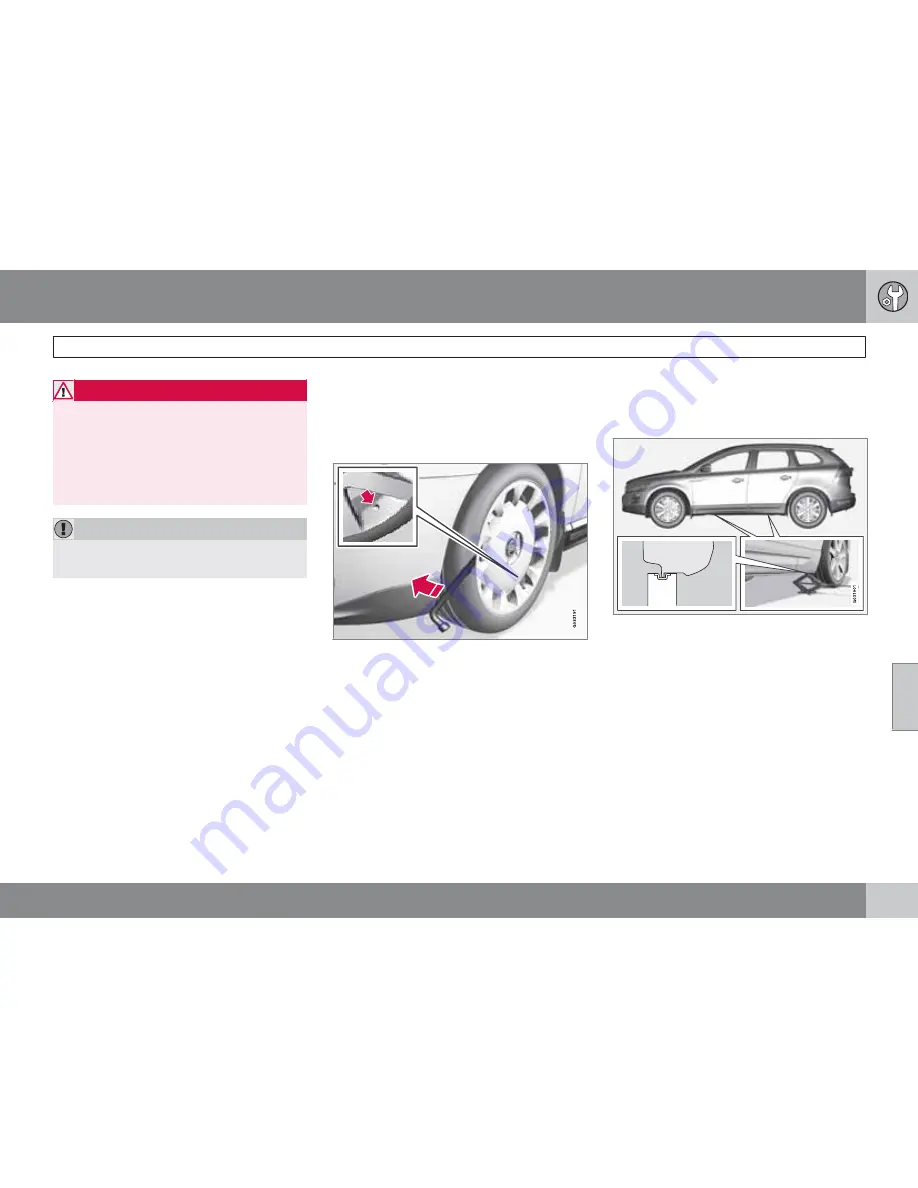
Removing the wheel cover
Changing a tire:
1.
Apply the parking brake.
2.
Put the gear selector in
P
.
3.
Block the wheels that are on the ground
with wooden blocks or large stones.
4.
Remove the wheel cover (where applica-
ble) using the lug wrench in the tool
bag.With the vehicle still on the ground,
use the lug wrench to loosen the wheel
nuts 1/2 – 1 turns by exerting downward
pressure.
5.
Turn the nuts counterclockwise to loosen.
6.
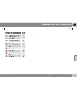
There are two jack attachment points on
each side of the vehicle. Position the jack
correctly in the attachment (see illustration
above) and crank while simultaneously
guiding the base of the jack to the ground.
The base of the jack must be flat on a level,
firm, non-slippery surface. Before raising
the vehicle, check that the jack is still cor-
rectly positioned in the attachment.
7.
Raise the vehicle until the wheel to be
changed is lifted off the ground.
Summary of Contents for XC60 2009
Page 1: ...VOLVO XC60 Owner s Manual Web Edition...
Page 2: ......
Page 7: ...Contents 7...
Page 15: ...01 SAFETY...
Page 53: ...01 Safety 01 53...
Page 54: ...54 Remote key and key blade 56 Keyless drive 63 Locks 66 Alarm 68...
Page 55: ...02 LOCKS AND ALARM...
Page 71: ...02 Locks and alarm 02 71...
Page 73: ...03 YOUR DRIVING ENVIRONMENT...
Page 74: ...03 Your driving environment Instruments and controls 03 74 Instrument overview...
Page 123: ...04 COMFORT AND DRIVING PLEASURE...
Page 200: ...04 Comfort and driving pleasure Passenger compartment convenience 04 200 Storage spaces...
Page 205: ...05 DURING YOUR TRIP...
Page 225: ...05 During your trip 05 225...
Page 227: ...06 MAINTENANCE AND SPECIFICATIONS...
Page 250: ...06 Maintenance and specifications Fuses 06 250 Engine compartment...
Page 284: ...06 Maintenance and specifications Label information 06 284 Location of labels...
Page 302: ...07 Index 07 302...
Page 303: ......
Page 304: ...Kdakd 8Vg 8dgedgVi dc IE JH6 8VcVYV 6I Eg ciZY c HlZYZc iZWdg 8deng i Kdakd 8Vg 8dgedgVi dc...


