2
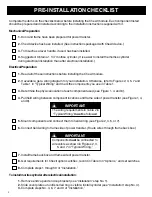
Complete the items on the checklist below before installing the Chexit module. Each component listed
should be prepared and installed according to the installation instructions supplied with it.
Mechanical Preparation
1.
Door and frame have been prepared for power transfer.
2.
Chexit device has been installed. (See instructions packaged with Chexit device.)
3.
Trim such as a lever handle, if used, has been installed.
4.
Suggested: Obtain a 1 1/4” mortise cylinder. (It is easier to install the mortise cylinder
during electrical installation than after electrical installation.)
Electrical Preparation
1.
Read all of these instructions before installing the Chexit module.
2.
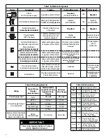
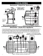
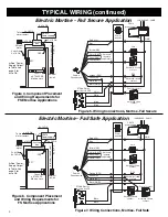
If available, get a wiring diagram for your installation. Otherwise, refer to Figures 2, 3, 5, 7 and
Table 1 in “Typical Wiring” and mark the components you use in Table 1.
3.
Determine the physical location of each component used (see Figure 1, 4, and 6).
4.
Pull field wiring between component locations and frame side of power transfer (see Figure 1, 4,
and 6).
5.
Mount components and connect them to field wiring (see Figure 2, 3, 5, or 7).
6.
Connect field wiring to frame side of power transfer. (Route wires through frame back box.)
7.
Install frame back box and frame side of power transfer.
8.
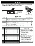
Get requirements for Chexit option switches, record in Table 3 in “Options,” and set switches.
9.
Complete steps 1 through 9 of “Installation.”
To install mortise cylinder after electrical installation:
1.
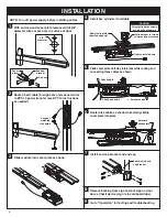
Remove end cap and end cap bracket (see “Installation” step No. 1).
2.
Slide cover plate out until knurled ring is visible; install cylinder (see “Installation” step No. 4).
3.
Complete steps No. 4, 6, 7, and 9 of “Installation.”
Components
must
be connected to
wire colors as shown in Figures 2, 3,
5, and 7 in “Typical Wiring.”
IMPORTANT
!
The wiring requirements in Table 2 in
“Typical Wiring”
must
be followed.
IMPORTANT
!
PRE-INSTALLATION CHECKLIST


