background image

4

FIRE

PS914

power supply

120/240VAC - 2 AMP

+24

GND

Horn

Normally

closed contact

Normally

closed contact

Normally

closed contact

Red (+24)

Blue (C)

Brown (NO)

Violet (CM-)

Gray (CM+)

Yellow (FA)

Orange (DPS)

Green (El)

White (SC)

Black (GND)

Cable to

Chexit
device

}

Not used;
insulate
separately

Power

transfer

3 x 14 GA

2 x

*

2 x 18 GA

2 x 18 GA

2 x 18 GA

(plus po

w

er if required)

2 x 18 GA

2 x     GA
5 x 18 GA

*

To fire
alarm contact 

Chexit

DPS

Junction

box

External

alarm

EPT

External

inhibit

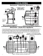
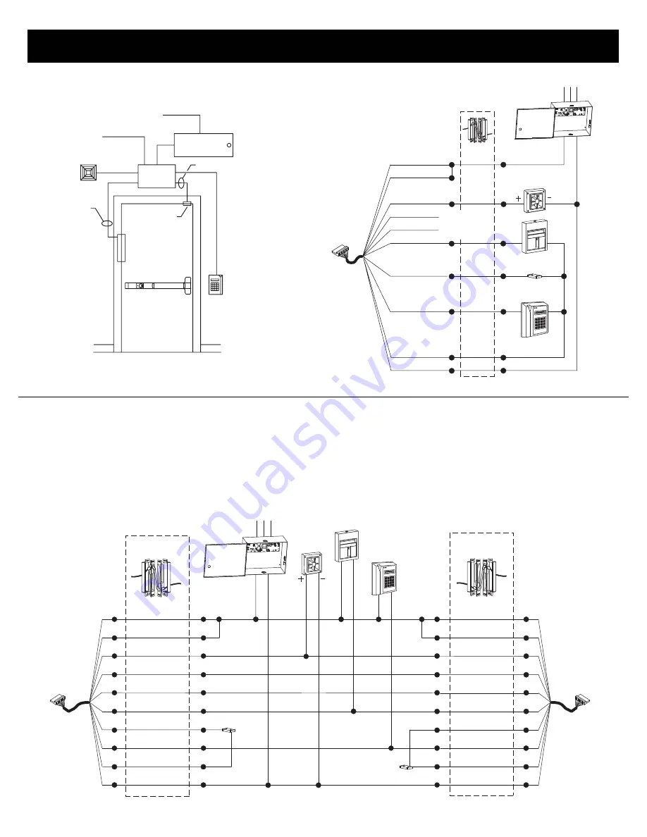
Rim/Vertical - Double Door Application

Figure 3. Wiring Connections, Double Doors

Rim/Vertical - Single Door Application

Figure 2. Wiring Connections, Single Door

Figure 1. Component Placement and

Wiring Requirements, Single Door

*

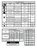
See tables 1, 2, and 3 on

page 3 for details

regarding components

and wire requirements

  See “Power

Supply Output”
in Table 2 on
page 3 for
wire GA

FIRE

120/240VAC - 2 AMP

+24

GND

Power

transfer

Horn

Normally

closed contact

Normally

closed

contact

Normally

closed contact

Red (+24)

Blue (C)

Brown (NO)

Violet (CM-)

Gray (CM+)

Yellow (FA)

Orange (DPS)

Green (El)

White (SC)

Black (GND)

Cable to

Chexit
device

Normally

closed contact

Red (+24)

Blue (C)

Brown (NO)

Violet (CM-)

Gray (CM+)

Yellow (FA)

Orange (DPS)

Green (El)

White (SC)

Black (GND)

Power

transfer

Cable to

Chexit
device

In this double door application, both doors open in the same direction and each is equipped with a Chexit. The two Chexits are
connected (ganged) by the gray (CM+) and violet (CM-) wires. 

(If not used, insulate these wires separately.)

 When one

Chexit is set into alarm, the other also goes into alarm, and both unlock after 15 seconds. A fire alarm unlocks both doors at
the same time. An external inhibit device also unlocks both doors at the same time. After an external inhibit, the door that
was used rearms 2 seconds after closing, and the unused door rearms after the full rearm time. 

For proper operation, the

rearm times of ganged Chexits must differ by at least 2 seconds.

See tables 1, 2, and 3 on page 3 for details

regarding components and wire requirements

TYPICAL WIRING

PS914
Power supply

PS914
power 
supply

Summary of Contents for CX33A

Page 1: ...RNING GENERAL INFORMATION ELECTRICALSPECIFICATIONS Voltage 24 VDC Current Chexit 0 4 A Current Electric mortise 0 3 A Current on arming 300 mS 16 A in rush External alarm dry contacts NO and C 24 VDC 1 A rating Normally closed inputs Fire alarm FA required External inhibit EI Door position switch DPS The Von Duprin Chexit device is designed for accident hazard or fire exit applications It meets bo...

Page 2: ...ble 1 3 Determine the physical location of each component used see Figure 1 4 and 6 4 Pull field wiring between component locations and frame side of power transfer see Figure 1 4 and 6 5 Mount components and connect them to field wiring see Figure 2 3 5 or 7 6 Connect field wiring to frame side of power transfer Route wires through frame back box 7 Install frame back box and frame side of power t...

Page 3: ...and GND ExternalAlarm Fire Alarm Door Position Switch External Inhibit Device EPT 10 EPT 10 Electric Hinge Electric Hinge EPT 10 Electric Hinge N A Percode 100 feet 200 feet 75 feet 150 feet Percode 14 GA 12 GA 14 GA 12 GA 18 22 GA Not critical The wiring requirements in Table 2 above must be followed IMPORTANT E7500ElectricMortiseLock Servesaslockingdeviceon CXE9975mortiseapplications Optional fo...

Page 4: ...ly closed contact Normally closed contact Red 24 Blue C Brown NO Violet CM Gray CM Yellow FA Orange DPS Green El White SC Black GND Cable to Chexit device Normally closed contact Red 24 Blue C Brown NO Violet CM Gray CM Yellow FA Orange DPS Green El White SC Black GND Power transfer Cable to Chexit device In this double door application both doors open in the same direction and each is equipped wi...

Page 5: ... x E7500 FS Mortise Lock DPS Junction box External alarm EPT External inhibit Red 24 Blue Brown NO Violet CM Gray CM Yellow FA Orange DPS Green EI White SC Black GND Violet White Black Black Power transfer 24 GND Not used insulate separately FIRE Normally closed contact Normally closed contact Normally open contact PS914 power supply 120 240VAC 2AMP Cable to Chexit device E7500 Electric mortise lo...

Page 6: ...move backing from sign and put sign on door above Chexit device sign is in cardboard tube 9 Go to Operation for testing and troubleshooting Cable inside end cap bracket Orient cylinder as shown or unit will not operate CAUTION INSTALLATION Slide module into cover plate as shown 1 With end cap and cover plate removed drill 5 8 diameter wire access hole in surface of door 2 3 Route Chexit cable thro...

Page 7: ...reen and white wires 2 If external inhibit not used connect green and white wires together Red LED does not light Power not reaching Chexit Replace reset AC fuse circuit breaker check power supply input output voltages check input voltage at Chexit cable connector Red LED on solid then flashes fast andhornsounds 1 Pushpadpressed 2 Pushpadswitchdisconnected 1 Releasethepushpad 2 Connect pushpad swi...

Page 8: ...a door position switch is used the Chexit arms 2 5 seconds after the door closes 6 If you are using a door position switch but you want the full rearm time to expire before the Chexit arms call Technical Support at 1 877 671 7011 7 For proper operation the rearm time of each ganged Chexit must differ by at least 2 seconds Location of Chexit option switches OPTIONS Factory settings shown 8 Off 7 Of...

Reviews: