Page 5 of 8
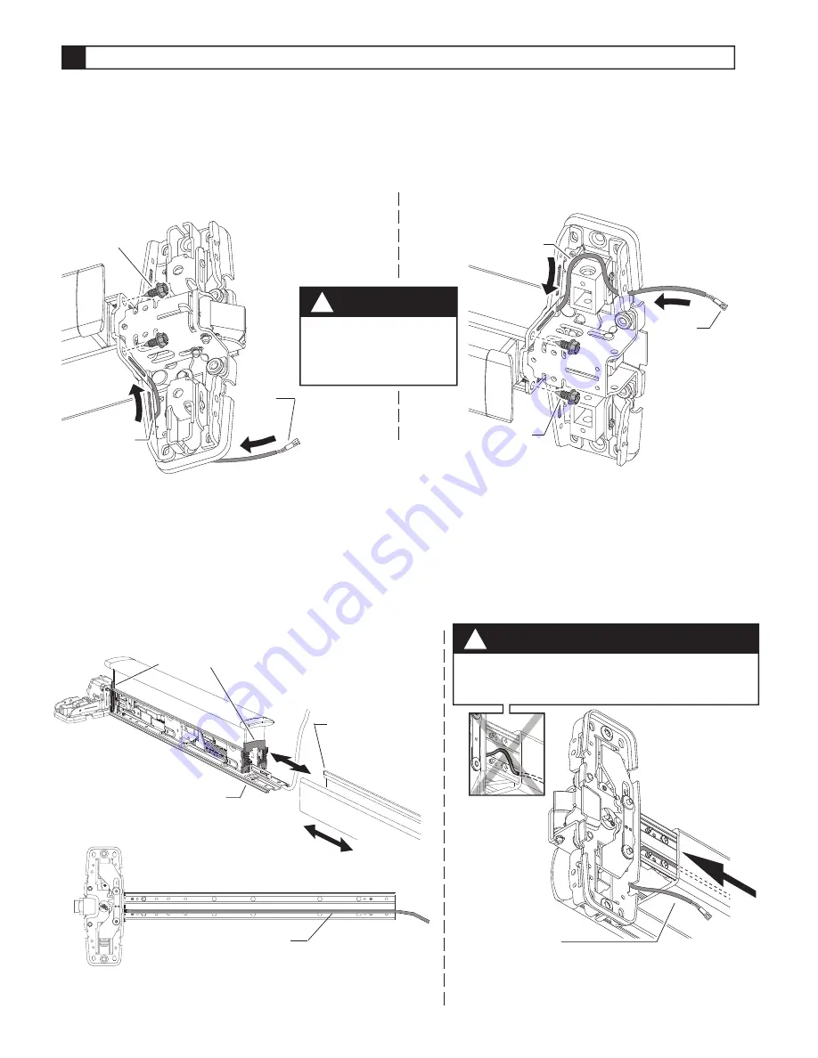
Route E996L cable through 98/99 series exit device.
7
Fig.7-3
7.2.
Slide mechanism case off baseplate assembly (Figure 7-2).
7.4.
7.5.
Slide mechanism case back on device. Align two plastic pushbar guides while installing
mechanism case (Figure 7-2).
7.6.
Slide mechanism case back against center case. Leave 4-6” of cable protruding from
center case end of device (Figure 7-4).
7.7.
Reinstall two mechanism case screws (Figure 7-1).
7.1.
Remove two mechanism case screws (Figure 7-1).
Fig.7-4
CAUTION
!
Be careful not to pinch cable when sliding
mechanism case back against center case.
7.3.
Route E996L cable through center case slots as shown (Figure 7-1). Cable plug should be on
door side of center case as shown (Figure 7-1).
Fig.7-1
RHRShown
(LHR Opposite)
98/99 Rim, 98/9927, &98/9975
98/9947
RHRShown
(LHR Opposite)
Fig.7-2
Mechanismcase
Pushbar guides
Baseplate
CAUTION
!
Ensure wire will not
interfere with moving
components.
Place E996L cable in groove on bottom of baseplate (Figure 7-3).
Optional:
Use electrical tape to hold cable in place.
Cable
plug
Cable
Mechanism
casescrews
Cable
plug
Cable
Mechanism
casescrews
Leave 4-6” of
cable protruding
(99 Rim shown)
Hold cable in groove
(or use electrical tape)


