background image

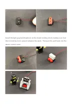
14.) Split the diagram into parts. Take a white 15cm lamp pellet with the connecting
wire facing the bayonet, install the lamp pellet on the stud, and fix it with a
transparent 1x1 round piece

Summary of Contents for P134

Page 1: ...ease refer to the online troubleshooting guide To ensure a smooth installation please read the installation steps carefully Package includes 7x 15cm white lamp pellets 2x 30cm white lamp pellets 3x white light bar 1x flame lamp module 3x 6 sockets 1x 5cm cable 3x 15cm cable 1x 30cm cable 1x AA battery box 1x round button battery box Extra pieces ...

Page 2: ... board is upward find the soldered sign on the left of the port When you are inserting the side which the wires can be seen should be faced to the sign and if you feel hard to insert please stop and don t force it for that may result in bent pins inside the port or overheating of the expansion board At this point use the tweezers to straighten the bent pins When installing dot lights make sure the...

Page 3: ... only one way With the Strip Light facing up ensure the side of the connector with the wires exposed is facing down If a plug won t fit easily into a port connector don t force it Doing so will damage the plug and the connector Finally please pay attention to the positive and negative terminals of the battery when installing the battery case ...

Page 4: ...Let s start ...

Page 5: ...1 Start with the lighting of the railway station First remove the train then remove the bridge and the lighting as shown ...

Page 6: ...ellet and pass its plug end through the transparent yellow building block as shown in the figure until the light emitting side of the lamp pellet is facing upwards and is located inside the building block Replace the black building block to fix it Live the lamp pellets ...

Page 7: ...Take another 30cm white lamp pellet repeat this step and install it to another lamp ...

Page 8: ... upper part of the wall pass the lighting connection line through the gap and install the lighting back to its original position Make sure that the connecting wire is placed between the studs as shown in the figure ...

Page 9: ...After installing the lighting install the wall back ...

Page 10: ...lace the light chip connection line down the wall Fix the connecting wire under the block as shown in the figure First remove the block as shown in the figure place the connecting wire between the lower studs and then reinstall the block ...

Page 11: ...t socket and insert the 2 lamp pellet connecting wires into the socket Install the battery in the battery box insert its connecting wire into 6 sockets turn on the power switch and test the effect of the lamp pellet ...

Page 12: ... out whether the problem is on the lamp pellet or the socket If there is a problem with the socket please read the online troubleshooting guide 4 Continue to install wall lighting First remove the lighting as shown in the figure and remove the black bayonet plate at the bottom ...

Page 13: ......

Page 14: ......

Page 15: ...stud Replace the lamp cover to secure it Pass the cable through the bayonet and pull it out from below 5 Lift the upper part of the wall slightly to create a gap between the walls and place the lamp chip connection line between the studs and pass through the gap Reinstall the lighting and then back to the wall ...

Page 16: ...k of the suit and pull down the connecting line along the wall Then remove the long black building block at the bottom insert the connecting wire into the socket turn on the power switch and check the lighting effect ...

Page 17: ...the lamp pellet does not light up you can change the socket to find out whether the problem is on the lamp pellet or the socket If there is a problem with the socket please read the online troubleshooting guide ...

Page 18: ...g wire insert one end of it into 6 sockets pull out the connecting wire from below and put it back into the long black building block Ensure that the lamp connection wire and 30cm connection wire are placed between the studs ...

Page 19: ...ecting line through the gap of the first step of the staircase and then pull the connecting line out from the front From front to back continue the connecting line through the next gap on the staircase and then from Pull out the cable from the back ...

Page 20: ...10 Separate the stairs part as shown to create a gap pass the connecting line through the gap pull the connecting line out from the other side and then close the gap ...

Page 21: ...f this part 11 Turn the bridge over and take a white 15cm lamp pellet and a transparent 2x2 round bottom plank Fix the lamp pellets on the top of the platform with a circular plate and make the connecting line face the bridge as the picture shows ...

Page 22: ......

Page 23: ...Behind the bridge create a gap in the middle of the bridge pass the connecting line through the gap make sure the connecting line is placed between the studs and close the gap ...

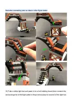
Page 24: ... connecting wire as shown in the figure below 12 Take a white light bar and paste it on a 1x6 building board then connect the connecting wire of the light pellet in the previous step to one end of the light bar ...

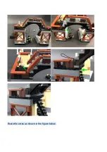
Page 25: ... Install the light bar to the position shown below the bridge Then install the bridge back to the railway station and wrap the excess part of the 15cm cable to the building plank of the light bar Tie the excess part of the 30cm connecting line and gather it into the space below the stairs ...

Page 26: ...Route the wires as shown in the figure below ...

Page 27: ......

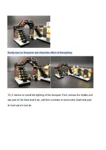
Page 28: ...and check the effect of the lighting 13 Continue to install the lighting of the train part First remove the middle and rear part of the illustrated train and then continue to remove the illustrated part of the front of the train ...

Page 29: ......

Page 30: ...14 Split the diagram into parts Take a white 15cm lamp pellet with the connecting wire facing the bayonet install the lamp pellet on the stud and fix it with a transparent 1x1 round piece ...

Page 31: ...Pass the cable through the bayonet and pull it out from below Put the part with the lamp pellets back on the black building block and then put the whole part back on the front of the train ...

Page 32: ...Make sure that the connecting wire is placed between the studs and then put the upper decorative part back 15 Split the part as shown ...

Page 33: ...llet and install it on the stud shown in the figure And use a transparent 1x1 round piece to fix it Repeat this step and then install a 15cm white lamp pellet to the following stud and also fix it with a transparent round piece ...

Page 34: ... the connecting wire is placed between the studs and replace the other parts that were previously split Then load this part back to the train 16 Turn the train to the side and remove the two parts shown in the figure ...

Page 35: ...Pass the 3 light chip connecting wires through the gap shown in the figure and insert them into 6 sockets ...

Page 36: ...17 Put the two previously removed parts back under the train Make sure the connecting wire is placed between the studs ...

Page 37: ...Take the round button battery box and install the battery Insert the battery box cable into 6 sockets turn on the power switch and test the lighting circuit ...

Page 38: ... socket please read the online troubleshooting guide 18 Remove the connecting wire of the round button battery box Use a lifter to remove the blocks shown in the figure from the rear of the train and then pull one of the 15cm connecting wires to the rear After making sure that the connecting wire is placed between the studs fix the connecting wire with black blocks ...

Page 39: ...pulling the excess connecting wires together fold them up as shown Pull the other 15cm cable backwards and upwards on the left side 19 Turn the train over and remove the part shown in the figure from the back ...

Page 40: ......

Page 41: ......

Page 42: ...15cm connecting wire on the left side between the studs and install a red 1x3 block on the top Place the connecting wire between the studs and fix it under the black and red building boards as shown in the figure ...

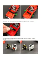
Page 43: ...20 Insert the 15cm cable into the input port of the flame lamp module Take the following part and remove the building block T shown on the back Split this part as shown ...

Page 44: ...21 Take 2 white 15cm lamp pellets install them on the two studs as shown in the figure and pull out their connecting wires upward and then fix the lamp pellets with a red building block ...

Page 45: ...Install the light gray building block on the black building block making sure that the connecting line is placed between the studs Then put this part back into the steam control room ...

Page 46: ...fully divide it into two parts from the bottom with scissors Then install the lamp pellets and put it back in place Insert the two light chip connecting wires into the output port of the flame lamp module and then install the steam chamber back to the train ...

Page 47: ...re and gather it inside the train 23 Plug the 15cm cable from the rear of the train into a new 6 seater socket Connect the round button battery box to the socket turn on the power switch to test the effect of the flame lamp module and lighting ...

Page 48: ...can change the socket to find out whether the problem is on the lamp pellet or the socket If there is a problem with the socket please read the online troubleshooting guide 23 Remove the 15cm cable from the socket and reinstall the remaining parts ...

Page 49: ...24 Take off the middle part of the carriage and remove the top and front walls Then put the car back into the front of the car and thread the 15cm cable into the interior ...

Page 50: ...d between the studs and then install the front wall back t 26 Take another 15cm cable and connect it to 6 sockets Take off the wall at the rear and pass the connecting line backwards Make sure the connecting wire is placed between the studs and then install the wall back ...

Page 51: ...Place the battery box inside the compartment and then put it back on top ...

Page 52: ...blocks shown in the figure so that we can remove the front wall Connect this car and the middle car to everything and then pull the 15cm connecting line to the last car Make sure that the connecting wire is placed between the studs and reinstall the front wall ...

Page 53: ...he blue building block as shown in the figure and the front wall and then reinstall the previously removed building tiles 28 Take 2 white light bars glue them to 2 1x6 building boards and connect them together with a 5cm connecting wire ...

Page 54: ...Install these two light bars to the position shown on the top 29 Insert the 15cm cable into the light bar then put it back on the top ...

Page 55: ...Turn on the power switch to test the effect of the cabin lighting The above is the installation process of this lighting set Turn on the power switch and enjoy it ...

Reviews: