background image

8

EN

WWW.VONROC.COM

DESCRIPTION

The numbers in the text refer to the diagrams on 

pages 2-4.

1. ON/OFF switch

2. Rear hand position

3. Motor housing

4. Front handle

5. Spindle lock button

6. Angle adjustment knob

7. Fence

8. Height adjustment knob

9. Cutting depth adjustment knob

10. Depth fine adjustment screw

11. Base plate

12. Dust extraction adapter

13. Dust bag

14. Spanner

15. Centerline

16. Biscuit dowel

17. Flange nut

18. Saw blade

19. Flange

20. Bottom plate

21. Angle scale and arrow

22. Height scale and arrow

3. ASSEMBLY

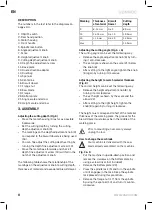
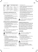
Adjusting the cutting depth (Fig.B)

•   Move the motor housing (3) as far as possible 

backwards.

•   Set the cutting depth by turning the cutting 

depth adjustment knob (9).

•   The markings on the depth adjustment knob (9) 

correspond to the biscuit dowel size being used 

(16).

•   You can fine adjust the cutting depth setting by 

turning the depth fine adjustment screw (10).

•   Move the motor base forwards and check if 

depth fine adjustment screw (10) will fall in the 

notch of the adjustment knob.

The following table shows the relationship of the 

markings on the adjustment knob to cutting depth, 

thickness of material and associated biscuit dowel.

Marking

Thickness 

of material

Biscuit 

Dowel

Cutting 

depth

0

8-12 mm

No. 0

8.0 mm

10

12-15 mm

No. 10

10.0 mm

20

> 15 mm

No. 20

12.3 mm

Max.

-

-

14.0 mm

Adjusting the cutting angle (Fig. A + G)

The cutting angle can be set the following way:

•   Release the angle adjustment knob (6) by turn-

ing it anti-clockwise

•   The set angle is shown on the scale (21) below 

the knob (6)

•   After setting to the right angle, tighten the knob 

(6) again by turning it clockwise. 

Adjusting the height to match material thickness 

(Fig. B)

The correct height can be set the following way:

•   Release the height adjustment knob (8) by 

turning it anti-clockwise

•   The set height is shown by the scale and the 

arrow (22).

•   After setting to the right height, tighten the 

knob (8) again by turning it clockwise. 

The height must correspond to half of the material 

thickness of the working piece, the groove for the 

biscuit dowel must always be in the middle of the 

working piece.

 Prior to mounting an accessory always 

unplug the tool.

How to change the saw blade

 Your machine is delivered with the saw 

blade already assembled on the machine

Fig. C & D

•   Put the machine in upside-down position and 

remove the 4 screws on the bottom plate by 

using a screw driver (not included)

•   Remove the bottom plate (20)

•   Press the spindle lock (5) and turn the spindle 

until it engages in the lock. Keep the spindle 

lock pressed during this procedure.

•   Remove the flange nut (17) from the spindle 

by using the spanner (14) and turn it counter-

clockwise.

Summary of Contents for BJ501AC

Page 1: ...ijke gebruiksaanwijzing 18 FR Traduction de la notice originale 25 ES Traducci n del manual original 32 IT Traduzione delle istruzioni originali 39 SV vers ttning av bruksanvisning i original 46 DA Ov...

Page 2: ...WWW VONROC COM 2 A B 8 22 9 10 13 12 14 15 8 1 3 2 3 6 11 4 5 7 16 10 9...

Page 3: ...WWW VONROC COM 3 C D E 19 14 20 18 5...

Page 4: ...WWW VONROC COM 4 F G 21 15...

Page 5: ...ug in any way Do not use any adapter plugs with earthed grounded power tools Unmodified plugs and matching outlets will reduce risk of electric shock b Avoid body contact with earthed or grounded surf...

Page 6: ...ep cutting tools sharp and clean Properly maintained cutting tools with sharp cutting edges are less likely to bind and are easier to control g Use the power tool accessories and tool bits etc in acco...

Page 7: ...tool is damaged it must be replaced by a specially prepared supply cord available through the service organization Using extension cables Only use an approved extension cable suitable for the power in...

Page 8: ...0 8 12 mm No 0 8 0 mm 10 12 15 mm No 10 10 0 mm 20 15 mm No 20 12 3 mm Max 14 0 mm Adjusting the cutting angle Fig A G The cutting angle can be set the following way Release the angle adjustment knob...

Page 9: ...each other Clamp the work pieces and mark the center of the groove by drawing a perpendicular line Several joints will be required for larger work pieces The distance between two drawn lines should be...

Page 10: ...lo ded view showing the parts that can be ordered ENVIRONMENT Faulty and or discarded electrical or electronic apparatus have to be collected at the appropriate recycling locations Only for EC countri...

Page 11: ...hrdeter Umgebung in der sich brennbare Fl ssigkeiten Gase oder Staub befinden Elek trowerkzeuge erzeugen Funken die den Staub oder die D mpfe entz nden k nnen c Halten Sie Kinder und andere Personen w...

Page 12: ...kzeugen zu ignorieren Eine unacht same Handlung kann innerhalb von Sekunden bruchteilen schwere Verletzungen verursachen 4 Sorgf ltiger Umgang und Gebrauch von Elektro werkzeugen a berlasten Sie das G...

Page 13: ...chine nicht bedienen Tragen Sie bei der Arbeit eine Sicherheitsbrille und einen Geh rschutz Falls erforderlich tragen Sie auch andere Schutzmittel beispielsweise eine Sch rze und einen Schutzhelm Vor...

Page 14: ...brationsbelastung erhe blich verringern Sch tzen Sie sich vor den Auswirkungen der Vibra tion durch Wartung des Werkzeugs und des Zube h rs halten Sie Ihre H nde warm und organisieren Sie Ihren Arbeit...

Page 15: ...rzeigersinn drehen Legen Sie den Scheibenfr ser 18 auf die Distanzbuchse 17 Achten Sie darauf dass der Pfeil auf dem Schei benfr ser in dieselbe Richtung zeigt wie der Pfeil im Geh useinneren Bringen...

Page 16: ...und warten sie auf das Aush rten des Klebstoffs Tipps zum Verbinden von zwei Werkst cken Fr sen Sie eine Nut in Gr e eines Flachd bels in das erste Werkst ck Bringen Sie den Flachd bel mit einem dem...

Page 17: ...t mehr im Gebrauch sind getrennt gesammelt und umweltfreundlich entsorgt werden GARANTIE VONROC Produkte werden nach den hochsten Qualitatsstandards entwickelt und sind fur den gesetzlich festgelegten...

Page 18: ...orzaken die deze stoffen tot ontbranding kunnen brengen c Wanneer u elektrisch gereedschap gebruikt houd dan kinderen en omstanders op afstand Wanneer u wordt afgeleid kunt u de controle over het gere...

Page 19: ...gereedschap Gebruik het juiste gereedschap voor uw specifieke toepassing Met het juiste elektrische gereedschap voert u de taak beter en veiliger uit wanneer dit op de snelheid ge beurt waarvoor het a...

Page 20: ...hermende middelen zoals een schort of een helm Haal altijd de stekker uit het stopcontact voordat u aan het apparaat zelf werkzaamheden uit gaat voeren Steek de stekker alleen in het stopcon tact als...

Page 21: ...neer de machine is uitgeschakeld of wan neer deze loopt maar geen werk verricht kan dit het blootstellingsniveau aanzienlijk reduce ren Bescherm uzelf tegen de gevolgen van trilling door de machine en...

Page 22: ...d de asvergrendeling tijdens deze procedure aange drukt Verwijder de flensmoer 17 van de as met de sleutel 14 en draai deze tegen de klok in Plaats het freesblad 18 op de flens 17 Zorg dat de pijl op...

Page 23: ...sleuf ter grootte van een lamello in het eerste werkstuk Plaats de lamello voorzien van de juiste soort lijm afhankelijk van het materiaal in de sleuf Frees een langere sleuf in het andere werkstuk N...

Page 24: ...jn ontworpen volgens de hoogste kwaliteitsstandaarden en gegarandeerd vrij van defecten zowel materieel als fabrieksfou ten tijdens de wettelijk vastgestelde garantiepe riode vanaf de eerste aankoopda...

Page 25: ...reils lectriques dans des environnements susceptibles d explosion par exemple en pr sence de liquides inflammables de gaz ou de particules Les appareils lec triques provoquent des tincelles qui peuven...

Page 26: ...engendrer de graves blessures en une fraction de seconde 4 Utilisation et entretien d un appareil lectrique a Ne forcez pas l appareil lectrique Utilisez l ap pareil lectrique ad quat pour votre appli...

Page 27: ...mement des deux mains et adoptez une position s re L utilisation de cette machine est interdite aux personnes de moins de 16 ans Portez toujours des lunettes de protection et un casque antibruit Au be...

Page 28: ...ccessoires diff rents ou mal entretenus peut consid rablement augmenter le niveau d exposition La mise hors tension de l outil et sa non utilisa tion pendant qu il est allum peuvent con sid rablement...

Page 29: ...rnie avec la lame de scie d j mont e sur la machine Fig C D Placez la machine en position retourn e et d montez les 4 vis sur la plaque inf rieure en utilisant un tournevis non fourni Retirez la plaqu...

Page 30: ...la pi ce sans ajouter une plaque d ajustement au dessous de votre pi ce fig G Assemblage des pieces Lorsque les rainures ont t faites dans les deux pi ces vous pouvez proc der l assemblage Mettez de l...

Page 31: ...hets domestiques Selon la directive europ enne 2012 19 EU D chets d quipements lectriques et lectroniques et sa mise en oeuvre dans le droit national les outils lectriques hors d usage doivent tre col...

Page 32: ...Mantenga a los ni os y otras personas alejados mientras utiliza la herramienta el ctrica Las distracciones pueden hacer que pierda el con trol de la herramienta 2 Seguridad el ctrica a Cerci rese de q...

Page 33: ...lizar un trabajo mejor y m s seguro si se utiliza para el objetivo con el que ha sido dise ada b No use herramientas que no pueden en cenderse o apagarse con el interruptor Las herramientas que ya no...

Page 34: ...a manualmente tras la desco nexi n La placa de base no debe estar retenida mientras la hoja est extendida El descenso y la subida de la hoja ha de ser una operaci n suave Utilizar siempre los escudos...

Page 35: ...6 Bot n de ajuste del ngulo 7 Gu a 8 Bot n de ajuste de altura 9 Bot n de ajuste de profundidad de corte 10 Tornillo de ajuste de precisi n de la profundidad 11 Placa de base 12 Adaptador de extracci...

Page 36: ...poner la m quina en funcionamien to aseg rese de que la parte superior de la placa de base est cerrada de forma segura Montaje de la bolsa para el polvo Fig A La bolsa para el polvo 13 puede utilizars...

Page 37: ...siguiente forma Mueva hacia atr s la estator del motor 3 tanto como sea posible Afloje la tuerca del tornillo de ajuste de precisi n mientras mantiene el tornillo en su posici n usando un destornillad...

Page 38: ...tar desde la fecha de compra original En caso de que el producto presente defectos relacionados con los materiales y o la fabricaci n durante este periodo p ngase directamente en contacto VONROC La pr...

Page 39: ...ntre si accende l arnese elettrico Le distrazioni possono farvi perdere il controllo 2 Sicurezza elettrica a Le spine dell arnese elettrico devono andare bene per la presa di corrente Non modificare m...

Page 40: ...ttivi fuori dalla portata dei bambini e non permettere a persone che non hanno confidenza con l arnese elettrico o con queste istruzioni di usare l arnese elettrico Gli arnesi elettrici sono pericolos...

Page 41: ...m quinas el ctricas deve sempre respeitar as normas de seguran a em vigor no local devido ao perigo de inc ndio de choques el ctricos ou ferimentos pessoais Para al m das instru es abaixo leia tamb m...

Page 42: ...la di regolazione fine della profondit 11 Piastra di base 12 Adattatore di aspirazione polveri 13 Sacca per polvere 14 Chiave 15 Linea centrale 16 Perno di centraggio a incastro 17 Dado della flangia...

Page 43: ...deve essere rivolto in su Rilasciare il blocco del mandrino e ruotare il mandrino per controllare che sia sbloccato Assemblare nuovamente la piastra inferior 20 e fissare le 4 viti Prima di mettere i...

Page 44: ...ere sempre la macchina nella stessa direzione del senso di rotazione Vedere la freccia sopra alla macchina Regolazione fine della profondit di taglio Fig B Seguire le istruzioni seguenti per corregger...

Page 45: ...dopera per il periodo contrattuale a partire dalla data di acquisto originale Qualora il prodotto dovesse subire un guasto qualsiasi durante questo periodo a causa di difetti nei materiali e o nella m...

Page 46: ...sa el uttaget ndra aldrig p n got s tt p stickkontakten Anv nd inte adapterkontakter till jordade elektriska verktyg Of r ndrade stickkontakter och passande uttag minskar risken f r el st tar b Undvik...

Page 47: ...erktygets funktion Om det elektriska verktyget r trasigt m ste det repareras innan det tas i bruk M nga olyckor f rorsakas av d ligt underh llna elektriska verktyg f H ll alltid s gande och sk rande v...

Page 48: ...erkarens kundservice Sl ng gamla kablar eller stickkontakter meddetsamma efter det att du har bytt ut dem mot nya Det r farligt att sticka in stickkontakten av en l s sladd i ett uttag Om str msladden...

Page 49: ...l Markering Material tjocklek Lamell Fr sdjup 0 8 12 mm No 0 8 0 mm 10 12 15 mm No 10 10 0 mm 20 15 mm No 20 12 3 mm Max 14 0 mm Justering av sk rvinkel Fig A G Sk rvinkeln kan st llas in p f ljande s...

Page 50: ...cm Sp rfr sning Fig F St ll in och kontrollera sk rdjupet p maskinen St ll in vinkeln p maskinen St ll in h jden p maskinen kontrollera att vid inst llning av h jden m ste sp ret f r kexdym lingen va...

Page 51: ...eller kasserade elektriska och elektroniska apparater ska l mnas in enligt g llande milj regler Endast f r EU l nder Sl ng inte elverktyg i hush llsavfallet Enligt det europeiska WEEE direktivet 2012...

Page 52: ...kiner Hvis man distraheres kan man miste kontrollen over den elektriske maskine 2 Elektrisk sikkerhed a Stik til elektriske maskiner skal passe til stik kontakten Der m ikke foretages ndringer af stik...

Page 53: ...eligt for b rn og personer der ikke har kendskab til den elektriske ma skine eller disse instruktioner m ikke bruge den elektriske maskine Elektriske maskiner er farlige i h nderne p u vede personer e...

Page 54: ...d og legemensbeskadigelse L s udover de neden st ende instruktioner ogs sikkerhedsforskrifterne i den separat vedlagte sikkerhedsfolder Kontroller altid om netsp ndingen svarer til v rdien p typeskil...

Page 55: ...lskala og pil 22 H jdeskala og pil 3 SAMLING Justering af fr sedybde Fig B Flyt motorhuset 3 s langt tilbage som muligt Indstil fr sedybden ved at dreje knappen til justering af fr sedybden 9 M rkerne...

Page 56: ...atisk stille sig p sluk 1 Brug aldrig spindell sen til at slukke for motoren Markering af arbejdsemnerne Fig E F r skyggefugefr seren t ndes skal arbejdsem nerne markeres p f lgende m de Anbring de to...

Page 57: ...at undg transportbeskadigelse leveres mas kinen i en solid emballage Emballagen er s vidt muligt lavet af genbrugsmateriale Genbrug derfor emballagen Defekte og eller kasserede elektriske eller elektr...

Page 58: ...rych atwo mo e doj do wybuchu np w obecno ci atwopalnych cieczy gaz w lub py u Podczas pracy elektronarz dzi akumulatorowych powstaj iskry kt re mog doprowadzi do zap onu py u lub opar w c Dzieci i i...

Page 59: ...elementy s u ce do odprowadzania i zbierania py u nale y sprawdzi czy s pod czone i czy dzia aj we w a ciwy spos b Korzystanie z tego typu element w pozwala ograniczy ryzyko zwi zane z wydzielaniem p...

Page 60: ...strzy p kni tych postrz pionych lub uszkod zonych w jakikolwiek inny spos b Nale y upewni si e materia przeznaczony do obr bki zosta odpowiednio zamocowany Zawsze utrzymywa r ce z daleka od obrabianej...

Page 61: ...a 14 mm Regulacja os ony 0 90 Ci ar 3 2 kg Lpa ci nienie akustyczne 87 dB A K 3dB Lwa moc akustyczna 98 dB A K 3dB Wibracje 2 695 1 5 m s2 Poziom drga Poziom emisji drga podany w tej instrukcji obs ug...

Page 62: ...wysoko ci nale y dokr ci pokr t o z powrotem 8 przekr caj c je zgodnie ze wskaz wkami zegara Przed instalacj akcesori w zawsze od czajcie narz dzie Spos b wymiany tarczy pi y Rys C D Maszyna jest dos...

Page 63: ...e W przypadku obrabianych przedmiot w o grubo ci mniejszej ni 16 mm wyci cie row ka po rodku obrabianego przedmiotu jest niemo liwe bez umieszczenia p ytki regulacyjnej pod obrabianym przedmiotem rys...

Page 64: ...dpowiedni spos b Tylko dla kraj w Komisji Europejskiej Nie wolno wyrzuca elektronarz dzi do domowych mietnik w Zgodnie z Dyrektyw Europejsk nr 2012 19 EU dotycz c Utylizacji Wyposa enia Elektrycznego...

Page 65: ...lectrice produc sc ntei care pot aprinde praful sau vaporii c n timpul lucrului cu o scul electric nu l sa i copiii sau privitorii s se apropie Mic orarea aten iei v poate face s pierde i controlul 2...

Page 66: ...l electric adecvat i va efectua mai bine i mai n siguran sarcina deoarece este folosi t la parametrii pentru care a fost proiectat b Nu folosi i scula electric n cazul n care co mutatorul de ac ionare...

Page 67: ...ai nt i techerul din priz nainte de a efectua orice opera ii asupra aparatului Con ecta i techerul numai c nd ma ina este oprit ine i cablul de alimentare la distan fa de raza de lucru a ma inii Manev...

Page 68: ...spate 3 Carcas motor 4 M ner frontal 5 Buton de blocare ax 6 Element de reglare a unghiului 7 Ghidaj 8 Butonul de reglare a n l imii 9 Buton de reglare a ad ncimii 10 urub de reglare fin a ad ncimii...

Page 69: ...trebuie s intre n lama discului partea plat trebuie orientat n sus Elibera i butonul de blocare al axului i verifica i dac butonul este deblocat rotindu l Asambla i din nou placa inferioar 20 i fixa...

Page 70: ...n sens invers acelor de ceasornic Mic ora i ad ncimea de t iere rotind urubul 10 n sensul acelor de ceasornic Repeta i procedura p n ad ncimea de taiere este corect Str nge i piuli a urubului de regl...

Page 71: ...le circumstan e sunt excluse de la aceast garan ie Repara iile sau modific rile care realizate sau care s au incercat a fi efectuate de centre de service neautorizate Uzura in condi ii normale Unealta...

Page 72: ...72...

Page 73: ...73...

Page 74: ...74...

Page 75: ...ricci n del uso de determinadas sustancias peligrosas en los equipos el ctricos y electr nicos IT Dichiariamo sotto la nostra responsabilit che questo prodotto conforme alle normative e ai regolamenti...

Page 76: ...2022 VONROC WWW VONROC COM 2203 01...

Reviews: