VopTel Technology Co., Ltd Page 14/67
Models
Number of FXS Ports
Number of FXO Ports
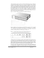
Figure 1-5
VG53X,VG54X Front Panel
Table 1-14
Description of VG53X,VG54X Front Panel
#
Description
①
Main control module. It offers one 10/100M Ethernet port and one
configuration interface (CON).
②
and
③
Two interface slots, and each can contain one desired type interface card.
Note: DO NOT plug or remove the main control module and interface cards of VG53X,VG54X when
equipment is powered on.
Table 1-15
Indicators of VG53X,VG54X
Mark
Function
Status
Description
Green Power
on
PWR
Power
Indication
Off Power
off
Off
System locked and inactive
Green Flash
Normal operation
Constant Red
System in the process of powerup and not in the
normal normal operation mode
STU
Status
Indication
Red Flash
System in a diagnostic mode and able to execute
limited operation
Green No
alarms
Red Flash
New alarms occurred but not confirmed
ALM
Alarm
Indication
Red
Alarms existed and all alarm information confirmed


