7
O
P
E
R
A
T
I
N
G
M
A
N
U
A
L
GB
Power supply connection
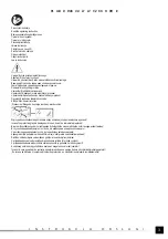
The power network of the lamp should be protected with a residual current device with a tripping current not exceeding 30 mA.
Connection of the power supply
It is required that the installation of lamp is carried out by a qualified electrician.
Before beginning installation, be sure to turn off the power supply from the mains, you which the lamp is connected! Failure to
comply to this recommendation may result in electric shock which can be the cause of serious injuries, and even death.
It is recommended that the grid, which is used for the lamp power supply, was protected by a residual current fuse breaker with a
tripping current of not more than 30 mA.
The lamp is equipped with a short cable that allows to connect it to the power supply of parameters listed in the table and in the
rating label.
The lamp should be connected so the degree of protection of the connection place would be equal or higher to the degree of
protection given in the lamp table and on the rating label.
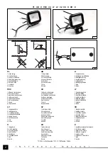
Veins of the cable should be connected in accordance with the colors of insulation (III).
If you need replacement of the cable, which is connected to the lamp, you should consult the authorized service depot.
Attention! It is forbidden to independently exchange the cable, which is connected to the lamp. The cable is connected the box
ensuring an adequate level of tightness. Unsealing of the box threatens by getting moisture to it, which could be the cause of
damage to the lamp and/or the mains, and also could cause electric shock, which can cause injuries or death. The manufacturer
does not take responsibility for damages resulting from independent replacement of cable connected to the lamp.
Adjustments of the movement sensor
The sensitivity of the sensor is the maximum distance from which the sensor may be activated. Turning the knob marked as
„SENS” clockwise increased the sensitivity, while turning it anticlockwise reduces the sensitivity.
The time for which the device remains active once it has been turned on may be adjusted within the range between 10 ± 3 seconds
to 10 ± 3 minutes. Turning the knob marked as „TIME” anticlockwise reduces the time, while turning it clockwise increased the
time. A movement of the knob towards the symbol „+”increased the time, while a movement towards „-” reduces the time.
Attention! When the light is turned on by the sensor, then each following movement will restart the countdown.
The illumination level adjustment module has a sensor device (a photocell), which detects light and darkness. It is possible to
adjust the operation of the sensor with the knob marked as „LUX”. The symbol of the sun indicates that the load will be activated
by the sensor both during the day and at night. The symbol of the moon indicates that the load will be activated by the sensor
solely at night.
ATTENTION!
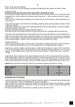
A delayed activation of the load in relation to the moment when the power supply is turned on is normal.
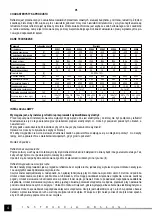
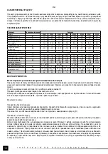
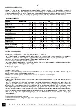
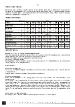
Parameter
Unit of measurement
Value
Assembly height
[m]
3
Detection angle
[
O
]
180
Detection range
[m]
10
Delay of time
[s]
10 ± 3 ÷ 600 ± 180
Grade of protection
IP54
SAFETY OF OPERATION
The electric installation of the lamp should be in good working order, and it must be periodically inspected, equipped with adequate
fuses. It should provide electric shock protection through immediate deactivation.
Do not ever use a lamp with visible mechanical damage, a power supply cable with damaged insulation, a broken glass of the
reflector and other visible damage. Any operations related to adjustments and installation must be realised with the power supply
of the lamp turned off.
Do not touch the housing of the reflector, since it heats up during work and may cause burns.


