Series S34 Instruction Manual
Chapter 6 Troubleshooting and Repair
M-000-00030
6-11
handheld unit and the SonoConnect™ breakout box. Verify that the wiring
connections inside of the SonoConnect™ breakout box match the pins
according to chapter 2 of the manual and that they are properly connected.
4.
The velocity cutoff (
Cutoff V)
is set too high. Go to the
First Level of the Hidden
Diagnostics
menu and record the
V
Value. The
Cutoff V
must be set below this
value.
5.
Verify all meter configuration and troubleshooting steps previously described.
There are many possible causes of this problem, consult factory if necessary.
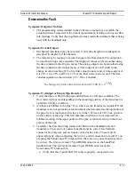
Symptom: Inaccurate Flow Rate Reading
1.
If the flow rate you are measuring is negative, the transducers/cables may have
been installed incorrectly. Verify the placement of the upstream and downstream
transducers and that the transducer cables are properly connected. The cable with
the red tag (upstream) must be connected to the upstream transducer and the
connector on the left of the top of the handheld unit labeled
UP
. The cable with
the blue tag (downstream) must be connected to the downstream transducer and
the connector on the right of the top of the handheld unit labeled
DN
.
2.
The first parameter to check when measuring a flow rate that is above/below the
expected flow rate of your system is the
SR Coefficient
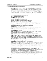
. This can be found in the
Second Level of the Hidden Diagnostics
menu.
a.
This parameter should be set to a value of 1.0 by default. If this value is not
set to 1.0 and you have not been instructed to change it, please change it
back to a value of 1.0. This value acts as a multiplier and will either increase
or decrease the flow rate displayed on the unit.
b.
If this value is set to 1.0 and the flow rate is still above/below the expected
flow rate, continue to the next step for additional parameters to consider.
3.
The next parameter to consider is the
Speed of Sound Source
. This can be found in
the
Calibration
menu. The SonoPro® gives the user the ability to select from
three different speed of sound sources which are used in the calculation to
determine the flow rate of the liquid inside the pipe.
a.
Spacing Temp
–
This
Speed of Sound Source
uses the temperature
programmed for determining the distance (spacing) between the scribe lines
of the transducers,
Spacing Temp
, to calculate the speed of sound.
b.
Fluid Temp 1
–
This
Speed of Sound Source
uses either a manual
temperature input (
Don’t Use RTD
) or measures the temperature from an
RTD (
Use RTD
) to calculate the speed of sound.
Use RTD
is a dynamic
value and will change with the change in temperature of the fluid.
Note:
This value can only be used if the user has a model that is compatible with
external RTD inputs (i.e. VER or VERER-EM).
c.
TOF_Calc
–
This
Speed of Sound Source
is measured with the two
transducers that are installed on the pipe. This is a dynamic value and will
change with a change in the measured up and down time of flight.
Summary of Contents for SonoPro S34 Series
Page 34: ...Series S34 Instruction Manual Chapter 3 Operation 3 5 M 000 00030 Output Menu...
Page 69: ...Series S34 Instruction Manual Appendix A Specifications A 2 M 000 00030...
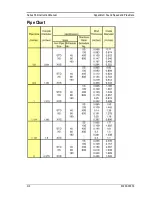
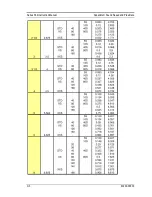
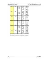
Page 73: ...Series S34 Instruction Manual Appendix C Sound Speed and Pipe Data C 2 M 000 00030 Pipe Chart...
Page 74: ...Series S34 Instruction Manual Appendix C Sound Speed and Pipe Data C 3 M 000 00030...
Page 75: ...Series S34 Instruction Manual Appendix C Sound Speed and Pipe Data C 4 M 000 00030...
Page 76: ...Series S34 Instruction Manual Appendix C Sound Speed and Pipe Data C 5 M 000 00030...
Page 77: ...Series S34 Instruction Manual Appendix C Sound Speed and Pipe Data C 6 M 000 00030...
Page 78: ...Series S34 Instruction Manual Appendix C Sound Speed and Pipe Data C 7 M 000 00030...
Page 79: ...Series S34 Instruction Manual Appendix C Sound Speed and Pipe Data C 8 M 000 00030...

