
V· ·f ;- -;-:
3.2 Necessary Tools
I.
Medium sized Phillips head screwdriver
2. Medium sized Flat-nosed screwdriver
3.3 Installation into an Amiga 2000
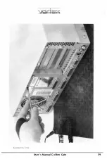
I. Remove all cables from the Amiga 2000 (including the power supply) and
place the computer in its normal position (view on the front side, floppy
disk drive(s) on the right) on the antistatic work place. Now remove the 5
screws connecting the upper part of the Amiga case with the lower part
with the Phillips head screwdriver and store them in a safe place (see
illustration 3.3.a). One screw is at the back and two screws each are on the
left and the right side in the lower part.
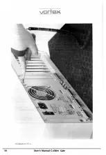
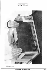
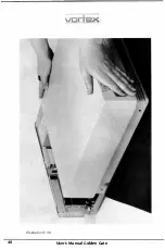
2. Carefully push forward the upper part of the case and lift it at the same
time. Please make sure that the upper part of the case does not become
entangled with cables in the interior of the Amiga and thus inadvertently
pull them out (see illustration 3.3.b). Put the upper part of the case in a
safe place.
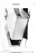
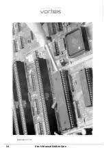
3. Golden Gate can be plugged into one of the bridge-slots of the Amiga (see
illustration 3.3.c). Before Golden Gate can be plugged in, the metal
bracket of the corresponding bridge-slot which closes off the Amiga case
at the back must be removed. Take out the corresponding screw with the
Phillips head screwdriver and remove the metal bracket. Store the screw
and the metal bracket in a safe place.
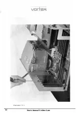
4. Now take Golden Gate out of the antistatic bag and plug it firmly into the
selected bridge-slot. If Golden Gate has been plugged in correctly, the
metal bracket fitted at the rear of Golden Gate over the two external
connectors neatly closes off again the Amiga case to the back. Tightly
connect the metal bracket with the Amiga case using the screw taken out
in step 3. (See illustration 3.3.d).
User's Manual Golden Gate
27
=
Summary of Contents for Golden Gate 386SX
Page 32: ...Illustration 3 3 a 30 V 1 User s Manual Golden Gate ...
Page 33: ...Illustration 3 3 b _ s s User s Manual Golden Gate 31 ...
Page 34: ...1 11 Illustration 3 3 c 32 User s Manual Golden Gate ...
Page 35: ... __ lSF Illustration 3 3 d User s Manual Golden Gate 33 ...
Page 36: ...Illustration 3 3 e 34 User s Manual Golden Gate ...
Page 37: ...Illustration 3 3 f User s Manual Golden Gate 35 ...
Page 41: ...Illustration 3 4 A _ _ User s Manual Golden Gate 39 ...
Page 42: ...Illustration 3 4 b 40 User s Manual Golden Gate ...
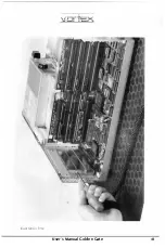
Page 43: ...Illustration 3 4 c ff r User s Manual Golden Gate 41 ...
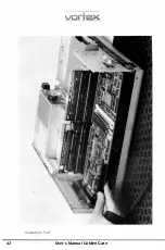
Page 44: ...Illustration 3 4 d 42 User s Manual Golden Gate ...
Page 48: ...illustration 3 5 b 46 User s Manual Golden Gate ...
Page 51: ...i lllust rat 1011 U a v r x 0 t1 0 t t1 1 0 User s Manual Golden Gate 49 I BOC38 ...
Page 52: ...y_ Illustration 3 6 b 50 User s Manual Golden Gate ...
Page 55: ...11 luslratlon 3 7 b F a User s Manual Golden Gate 53 ...
Page 57: ...VI VI 01 I Floppy Disk I I Illustration 3 7 d User s Manual Golden Gate ...
Page 59: ... 0 Illustration 3 8 a _Jr r j D I l I tJ I n User s Manual Golden Gate 0 57 ...


