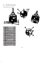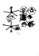
2.6 Description of the parts
Parts that make up the ceiling fan
12
Fig. 2
NUM.
DESCRIZIONE
Q.TA’
1
Motor rod holder
1
2
Welded rod holder
1
3
Tempered shaft hub
1
4
Fissing plate
1
5
Rod 50X50 drilled and galvanized
1
6
Washer 10.5X20 H2 galvanized UNI 6592
16
7
Self-locking nut M10 galvanized UNI 7474
12
8
Screw M10X45 TH galvanized UNI 4018
4
9
Screw 10X35 TH galvanized UNI 4018
2
10
Safety holder
2
11
Washer Grower D. 8 galvanized
4
12
Screw M8X25 TCH INOX
4
13
Washer 14X36 H2,5 galvanized UNI 6593
10
14
Screw M12X90 TH galvanized UNI 4014
5
15
Self-locking nut M12 galvanized UNI 7473
5
16
Washer Grower D.10 galvanized
2
17
Blade Support
1
18
Fan blade
5
19
Winglet
5
20
Washer 8,4X16 H6 galvanized UNI 6592
10
21
Self-locking nut M8 galvanized UNI 7473
25
22
Screw M8X50 TCH galvanized UNI 5931
15
23
Washer 8X24 H2 galvanized UNI 6593 FL
40
24
Screw M8X45 TCH galvanized UNI 5931
10
25
Reinforced spider spacer
1
26
Bottom cap
1
Summary of Contents for NORDIK HVLS SUPER BLADE 300/120
Page 1: ...NORDIK HVLS SUPER BLADE Instruction booklet COD 5 571 084 934 23 07 2021...
Page 23: ...23 Attachment 1 Assembly Instructions...
Page 34: ...34 Assembly rod holder and rod PLACE ROD INTO MOTOR HOLDER AND FIX WITH SCREWS NUTS AND BOLTS...
Page 52: ...52 Attachment 2 Electric connection...
Page 67: ...67 8 Connection Diagram with VORT T HCS Electric Scheme Option 3 VORT T HCS VORTICE Code 20151...
Page 70: ...70...


