background image

VORTICE S.p.A. si riserva il diritto di apportare tutte le varianti migliorative ai prodotti in corso di vendita.
VORTICE S.p.A. reserves the right to make improvements to products at any time and without prior notice.
VORTICE S.p.A. se réserve le droit d'apporter toutes les variations afin d'améliorer ses produits en cours de commercialisation.
VORTICE S.p.A. behält sich vor, alle eventuellen Verbesserungsänderungen an den Produkten des Verkaufsangebots vorzunehmen.
VORTICE S.p.A. se reserva el derecho a hacer cambios en los productos para su mejora en cualquier momento sin previo aviso.
VORTICE S.p.A. 

VORTICE S.p.A. 
Strada Cerca, 2 - frazione di Zoate 
20067 - Tribiano (MI) 
Tel. +39 02-90.69.91 
ITALY 
vortice.com 
postvendita@vortice-italy.com

VORTICE LIMITED
Beeches House-Eastern Avenue
Burton on Trent - DE 13 0BB
Tel. +44 1283-49.29.49
UNITED KINGDOM
vortice.ltd.uk
sales@vortice.ltd.uk

VORTICE INDUSTRIAL Srl 
Via B. Brugnoli, 3
37063 - Isola della Scala (VR)
Tel. +39 045 6631042
ITALY
vorticeindustrial.com
info@vorticeindustrial.com

VORTICE GROUP COMPANIES

CASALS VENTILACIÓN INDUSTRIAL IND., S.L.
Ctra. Camprodon, s/n
17860 - Sant Joan de les Abadesses (Girona)
SPAIN
casals.com 
ventilacion@casals.com

VORTICE VENTILATION SYSTEM (CHANGZHOU) CO.LTD
Building 19, No.388 West Huanghe Road, Xinbei District,
Changzhou, Jiangsu Province CAP:213000
CHINA
vortice-china.com
vortice@vortice-china.com

VORTICE LATAM S.A.
Bodega #6
Zona Franca Este Alajuela - Alajuela 20101
Tel. (+506) 2201 6934
COSTA RICA
vortice-latam.com
info@vortice-latam.com

Summary of Contents for NORDIK HVLS SUPER BLADE 300/120

Page 1: ...NORDIK HVLS SUPER BLADE Instruction booklet COD 5 571 084 934 23 07 2021...

Page 2: ...SEMBLY 15 5 INSTALLATION 16 5 1 Preliminary operations 16 5 2 Positioning 16 5 3 Optimum installation conditions 16 5 4 Tightening torque 17 5 5 Tie bars 17 5 6 Noise emissions 17 5 7 Cleaning 17 5 8...

Page 3: ...iately after it has stopped Remember that the motor could be hot Never immerse the equipment in water or any other liquid and do not use water especially pressur ised for washing or cleaning the fan o...

Page 4: ...tasked with installing operating set ting cleaning repairing moving or doing maintenance work on the machine QUALIFIED PERSONNEL QUALIFIED OPERATOR Person s that has have done a specialisation course...

Page 5: ...THER DEFINITIONS MAN MACHINE INTERACTION Any situation in which an operator interacts with the machine in any opera ting phase and at any time in the life of the machine OPERATOR S QUALIFICATION The m...

Page 6: ...ive devices deactivated and do work on the mechanical parts to effect the necessary adjustments maintenance and repairs Normally they are not authorised to work on live electrical systems Electrical m...

Page 7: ...pneumatic power supplies disconnected Machine running operating in automatic mode with mobile guards closed related interlocking devices activated and fixed guards closed Machine on stopped and ready...

Page 8: ...ON OBLIGATION Pictogram Name High voltage danger Entanglement Dragging General danger Do not remove the safety devices Cleaning oiling greasing repairing or adjusting moving parts manually forbidden O...

Page 9: ...gressive atmospheric conditions Use in atmospheric conditions with high salinity or humidity over 90 of that of the standard atmospheric air Use in places in which external suspended elements are pres...

Page 10: ...ntacting the manufacturer or service centres always quote these reference details The position of the plate on the machine may vary from one machine to another Fig 1 example data plate for SUPER BLADE...

Page 11: ...11 2 5 Declarations This machine was made in conformity with the pertinent European Directives applicable at the time it was put on the market EC Declaration of Conformity...

Page 12: ...UNI 4018 2 10 Safety holder 2 11 Washer Grower D 8 galvanized 4 12 Screw M8X25 TCH INOX 4 13 Washer 14X36 H2 5 galvanized UNI 6593 10 14 Screw M12X90 TH galvanized UNI 4014 5 15 Self locking nut M12 g...

Page 13: ...13 Fig 3 Bottom cap 1 14 13 7 6 7 6 13 15 18 23 21 8 6 9 16 4 25 22 17 20 19 26 24 21 24 2 5 13 15 14...

Page 14: ...er having checked that the necessary suitable equipment is available They must have personal protection equipment required for the task and called for by applicable local norms Also given the weight o...

Page 15: ...hin 15 days of discovering the fault in the product Malfunctioning of the ceiling fan due to faults in components and or irregularities relating to parts of the product not reported immediately in the...

Page 16: ...an accessible place that allows regular functioning to be checked visually at all times from the ground It must also allow quick stoppage in case of emergency as well as correct routine and extraordi...

Page 17: ...he side with wind speeds greater than or equal to 14 m sec is expressly forbidden For wind speeds of between 10 and 14 m sec use of the tie bar kit for installation is obligatory and the machine is al...

Page 18: ...ave been completed power the machine and wait for about 30 seconds to allow it to complete a self diagnosis of its default parameters and then start rotating Subsequently check that There is no imbala...

Page 19: ...2 3 Yearly 1 2 3 4 2 Years 1 2 3 4 5 5 Years 1 2 3 4 5 6 Activity legend 1 Visual check Check direction of rotation Check abnormal vibrations Check LED operation 2 Check structural integrity Check sta...

Page 20: ...e side of the blades of about 1 m while below the machine there must be no impediment within about 2 7 m of the fan Maintenance records We believe that for safe use of the product it is important that...

Page 21: ...eference as shown in the drawing Quantities of parts ordered Client s address pos descrizione codice 1 Motor Inverter Motor Nordik 300 120 1 241 000 263 Motor Nordik 400 160 1 241 000 263 Motor Nordik...

Page 22: ...on or the mains power supply The fan does not start The power supply to the motor is not on Check the electricity supply to the motor The motor is faulty Contact specialist authorised personnel to rep...

Page 23: ...23 Attachment 1 Assembly Instructions...

Page 24: ...24 Assembly blade support to motor STAR BLADE SUPPORT FIXING PLATE DISK HUB SCREW M10x45 TE SELFBLOCK BOLT M10 NUTS 10 5x20 h2 SCREW M10x35 TE NUTS GROWER D 10...

Page 25: ...25 Assembly blade support to motor INSERT PLATE INTO BLADE SUPPORT USING SCREWS M10x45 TE NUT 10 5x20 h2 ATTENTION Check right side of the star Blade Support...

Page 26: ...26 Assembly blade support to motor ATTENTION Place hub with tab seats oriented as per pic ture at side POSITION HUB AND CLOSE NUTS 10 5x20 h2 TO SELFBLOCKING BOLT M10...

Page 27: ...27 Assembly Blade Support on Motor PLACE BLADE SUPPORT WITH DISC OVER THE SHAFT AND CLAMP SCREWS M10x35 TE WITH NUTS GROWER D 10...

Page 28: ...28 Safety holder assembly when needed SAFETY HOLDER SCREW M8x25 TCEI INOX already available into motor NUT GROWER D 8 already available into motor...

Page 29: ...29 Safety holder assembly when needed PLACE SAFETY HOLDER AND FIX THEM WITH SCREWS Already available into motor...

Page 30: ...30 Assembly motor holder MOTOR HOLDER SELFBLOCKING BOLT M10 NUT 10 5x20 h2 POSITION MOTOR HOLDER OVER MOTOR CLAMP NUTS AND BOLTS...

Page 31: ...Assembly Winglet on blade POSITION THE WINGLET AT BLADE TIP FIX WITH PROVIDED SCREWS and NUTS WINGLET SCREW M8x45 TCEI WASHER 8 4x16 h1 6 SELFBLOCKING BOLT M8 BLADE Code indicated in the Component tab...

Page 32: ...nal destination SCREW M8x60 TCEI NUT 8 4x24 h2 SELFBLOCKING BOLT M8 Blade s top face fixed with selfblocking Bolts ATTENTION Screws must be assembled with the head of the screw on the bottom face of e...

Page 33: ...mbly rod holder and rod ROD HOLDER SCREW M12x90 TE NUT D 14x36 h2 5 SELFBLOCKING BOLT M12 ROD SCREW M12x90 TE NUT D 14x36 h2 5 SELFBLOCKING BOLT M12 ATTENTION Rod holder position is in rod side with 2...

Page 34: ...34 Assembly rod holder and rod PLACE ROD INTO MOTOR HOLDER AND FIX WITH SCREWS NUTS AND BOLTS...

Page 35: ...lder and rod PLACE ROD INTO ROD HOLDER AND FIX WITH SCREW NUTS AND BOLTS ASSEMBLY POSITION FOR ROD HOLDER DEPENDS ON INSTALLATION STUDY AND DESIGN z5 z5 z5 z5 240 240 47 5 O 1 3 x 4 40 75 40 190 190 4...

Page 36: ...tar blade holder Material Main star blade holder Reinforced star blade holder folded spacer SCREW M8x45 TCEI NUT 8 4x24 h2 SELFBL BOLT M8 To assemble 5 central screws Rein for ced Spider to Main Spide...

Page 37: ...he Main Star blade holder to the Hub Put the blades in the Main Star blade holer s spokes centering the blade mounting holes by using a screwdriver Fix without tightening the external screw for each b...

Page 38: ...e wi thout tightening with bolts and nuts Tight the 5 central screws already fixed Tight the screws to fix the blades Put the hooks of the bottom cap into the holes of the spacer N B The M8 screws tig...

Page 39: ...hine and wait about 30 seconds until it start to run be cause machine need 30 seconds to autoset all parmeters After that check following No rotation unbalancing due to wrong components assembly No no...

Page 40: ...40 Assembly PCB on motor Possible to do also with motor fixed to the roof PC BOARD POWER AND SIGNAL CONNECTORS M6x16 TCEI...

Page 41: ...tion USE AROUND THE CABLE ONE SHEATH TO INCREASE THICKNESS AND HAVE OPTIMUM CLO SING IT S MANDATORY TO PROTECT THE BACK PART OF CONNECTORS FROM HUMIDITY OR DIRT USING INSULATING COIL OR SOME OTHER MAT...

Page 42: ...Kit Cod 20193 HVLS SUPER BLADE RD No DESCRIPTION Q TA 1 CAST IRON CLAMP 8 2 M8 VERZINKT SPANNER 4 3 GALVANIZED CABLE 49THREADS DIAM 5 20 m 4 M8 ANCHOR BOLT 4 45 A B DETAIL A 2 3 DETAIL B B A B C TOP V...

Page 43: ...mbly PCB on motor Possible to do also with motor fixed to the roof M6x16 TCEI Lean Pc Board to connect power line and probe ATTENTION to colours U BLACK V GREY W BROWN Assembly PC board to motor and c...

Page 44: ...44 DISCONNECT POWER DISCONNECT BOTH OF TWO CONNECTORS FROM FAN Diassembly Fan POWER Operation with motoinverter connectet to the roof...

Page 45: ...er connectet to the roof SCREW M8x60 TCEI NUT 8 4x24 h2 SELFBLOCKING BOLT M8 UNSCREW AND DISASSEMBLY BLADES ATTENTION Operation require you use adequate support to substain blades and their weight so...

Page 46: ...46 Disassembly fan WINGLET Operation to be made with blade to the ground Loosen the screw fissing the plastic Winglet to the blade WINGLET SCREW M8x45 TCEI WASHER 8 4x16 h6 SELFBLOCKING BOLT M8 BLADE...

Page 47: ...motoin ver ter fixed to the roof SCREW M12x90 TE NUT D 14x36 h2 5 SELFBLOC BOLT M12 UNSCREW MOTOR HOLDER FROM ROD ATTENTION Operation require you use adequate support to substain blades and their weig...

Page 48: ...s support Operation with Motoinverter on floor MOTOR HOLDER SELFBLOCKING BOLT M10 NUT 10 5x20 h2 ATTENTION Use adequate support to avoid support blade to be direct in contact with floor UNSCREW MOTOR...

Page 49: ...with Motoinverter on floor SCREW M10x45 TE SELFBLOCKING BOLT M10 NUT 10 5x20 h2 SCREW M10x35 TE NUT GROWER D 10 MAIN SPIDER FIXING BLADE UNSCREW BLADE SUPPORT FROM SHAFT AND HUB AND TAKE OUT PARTS ATT...

Page 50: ...EW M8x25 TCEI SS already on the motor NUT GROWER D 8 already on the motor ATTENTION A The Hub is strongly connected to the shaft You will need adequate extractor B If present safety holder before unsc...

Page 51: ...PCB Operation with Motoinverter to the floor or fixed to the roof ROTATE FOR 180 THE MOTOR UNSCREW THE SCREWS DISCONNECT CABLE PCB M6x16 TCEI ATTENTION Avoid to place directly in contact shaft with fl...

Page 52: ...52 Attachment 2 Electric connection...

Page 53: ...ure the proper operating of the differential pro tections installed in accordance with regulations about indirect contact and no dissipation of stray currents Attention line with MT D magnetotermic pr...

Page 54: ...actions Many maintenance interventions and diagnostic actions of the fan can be done by remote connection In order to do this it is however necessary to identify exactly the fan and connect to it The...

Page 55: ...55 Modbus Address label Motoinverter type and Serial Num ber label Inverter parameterization Blades Diameter Set label...

Page 56: ...NORDIK HVLS SUPER BLADE 400 160 61081 NORDIK HVLS SUPER BLADE 400 160 L 61091 NORDIK HVLS SUPER BLADE 500 200 61082 NORDIK HVLS SUPER BLADE 500 200 L 61092 NORDIK HVLS SUPER BLADE 600 240 61083 NORDIK...

Page 57: ...ion scheme 3 Connection schemes THREE POLAR CABLE CAVO MONOFASE PE SINGLE PHASE CABLE PE 4 coppie totale 8 cavi 4 twins tot 8 wires CENTRALINA ALIMENTAZIONE POWER BOX 200 480V TRIFASE 50 60 Hz 220 240...

Page 58: ...di 2 mA Dedicated line suitably protected with Magnetic Thermical Switch and Differential Class A with a sensitivity of 300 mA The line must be taken downstream of the main switch of the system and b...

Page 59: ...Hz MAIN SWITCH MT and Differential type A POWER BOX 220V MONOFASE 50 60 Hz 220V SINGLE PHASE 50 60 Hz CAVO TRIPOLARE PE THREE POLAR CABLE PE LINEA ALIMENTAZIONE 220 240V MONOFASE 50 60 Hz SUPPLY LINE...

Page 60: ...60 Multi wire diagram for system wiring three phase SUPPLY LINE 200 480V THREE PHASE 50 60 Hz MAIN SWITCH MT and Differential type A POWER BOX THREE POLAR CABLE PE...

Page 61: ...IN 0 10V 6 10V I USATO COL POTENZIOMETRO 7 GND SCHERMATURA PIN 1 2 3 4 IN OUT CONNECTOR CONNETTORE SEGNALE MONO POLAR SUPPLY CONNECTOR CONNETTORE ALIMENTAZIONE MONOFASE GIALLO VERDE MARRONE GRIGIO 1...

Page 62: ...E PHASE SUPPLY CONNECTOR CONNETTORE ALIMENTAZIONE TRIFASE MARRONE NERO GRIGIO GIALLO VERDE SWITCH RELAY reverse rotation rotazione inversa INTERRUTTORE RELE THREE PHASE SUPPLY CONNECTOR CONNETTORE ALI...

Page 63: ...0 Kohm GND I MODBUS A MODBUS B ANALOGIC IN 0 10V DETTAGLIO CONNESSIONI SUPPLY CONNECTOR THREE PHASE SINGLE PHASE CONNETTORE ALIMENTAZIONE MONOFASE SUPPLY CONNECTOR SINGLE PHASE 63 NB It is necessary p...

Page 64: ...0V DETTAGLIO CONNESSIONI CONNETTORE ALIMENTAZIONE MONOFASE SUPPLY CONNECTOR SINGLE PHASE CONNETTORE ALIMENTAZIONE TRIFASE SUPPLY CONNECTOR THREE PHASE 64 NB It is necessary pull the A and B wires down...

Page 65: ...RT T Control Box VORTICE Code 21137 6 Connection Diagram with VORT T Control Unit 3 4 5 1 2 6 7 ANALOGIC IN 0 10 V MODBUS B MODBUS A IN OUT CONNECTOR CONNETTORE SEGNALE GND I SCHERMATURA SHIELD 19 18...

Page 66: ...66 7 Connection Diagram with VORT T PLUS Electric Scheme Option 4 VORT T PLUS VORTICE Code 20152...

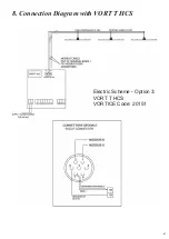
Page 67: ...67 8 Connection Diagram with VORT T HCS Electric Scheme Option 3 VORT T HCS VORTICE Code 20151...

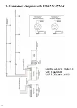
Page 68: ...68 9 Connection Diagram with VORT MASTER Electric Scheme Option 3 VORT MASTER VORTICE Code 20153...

Page 69: ...gnosis of default parameters and to start rotating Then check that there are no installation imbalances due to incorrect assembly of the components or latent their defects there are no metallic noises...

Page 70: ...70...

Page 71: ...ernatively the distributor is obliged to take back the appliance to be disposed of free of charge in exchange for the purchase of an equivalent appliance WARNINGS This appliance can be used by childre...

Page 72: ...67 Tribiano MI Tel 39 02 90 69 91 ITALY vortice com postvendita vortice italy com VORTICE LIMITED Beeches House Eastern Avenue Burton on Trent DE 13 0BB Tel 44 1283 49 29 49 UNITED KINGDOM vortice ltd...

Reviews: