


30
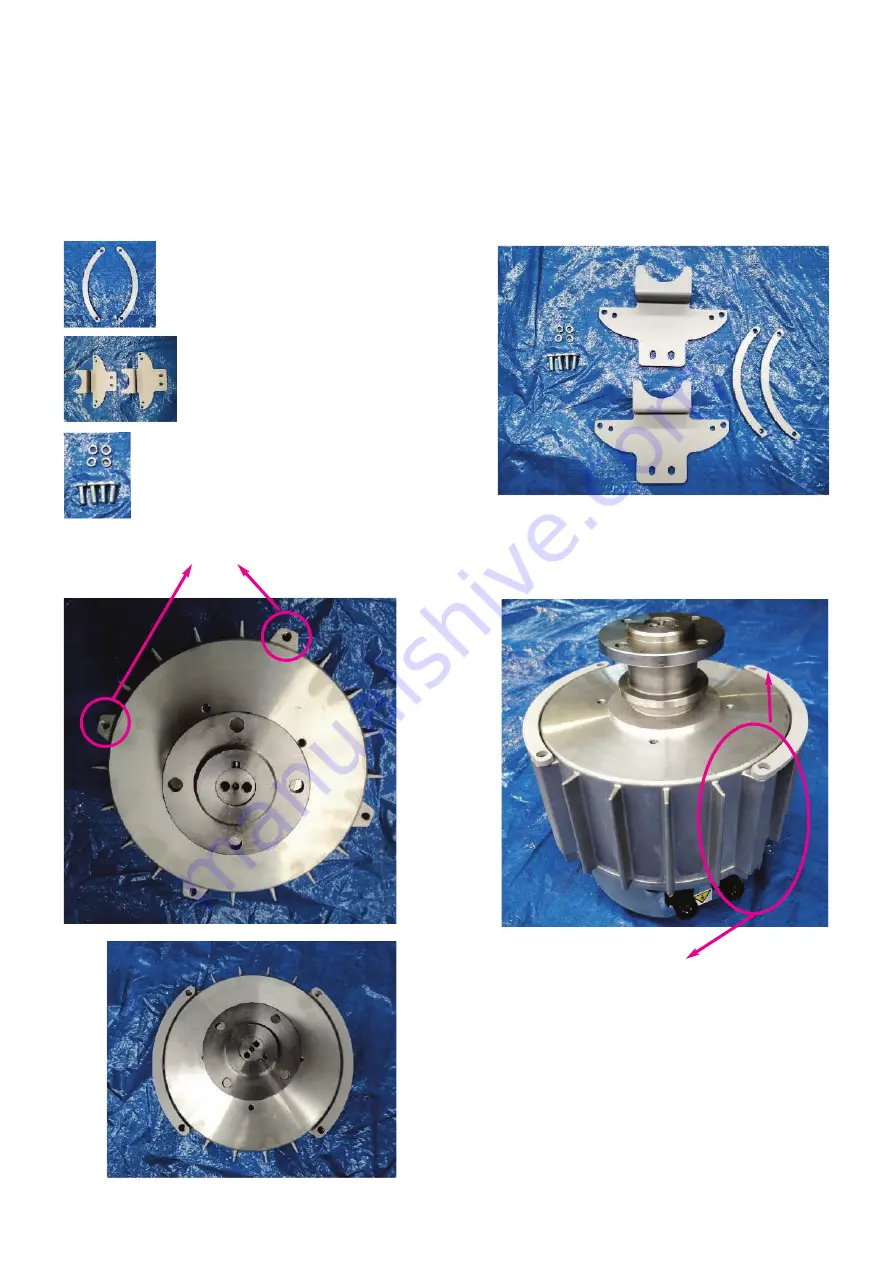
Fall protection plate assembly
Position the fall protection plate shims on the corresponding fixing holes of the motor,
aligning one shim hole with the 7-pin connector and the second with the next hole
on the right of the connector (as shown in the images).
2 FALL PROTECTION SHIMS
2 FALL PROTECTION PLATES
4 GROWN WASHER DIAM. 8 GALV
4 SCREWS M8X25 TE GALV
Fixing holes
CAUTION!
Verify the correct alignment
as indicated
Summary of Contents for Nordik HVSL Super Blade 110 V Series
Page 1: ...NORDIK HVLS SUPER BLADE E SUPER BLADE 110 V Instruction booklet COD 5 571 084 939 23 07 2021 ...
Page 25: ...25 INVERTER MOTOR ELECTRONICS QUICK CONNECTORS ...
Page 28: ...28 Destratification Fan assembly ...
Page 56: ...56 Attachment 2 Electric connection ...
Page 67: ...67 Multi wire diagram for system wiring SINGLE PHASE 85 264V 50 60 Hz ...
Page 78: ......
Page 79: ......


