70
VOR-12832
1
2
3
4
5
6
7
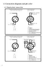
+10V-I
1
2
3
4
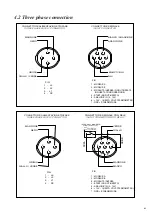
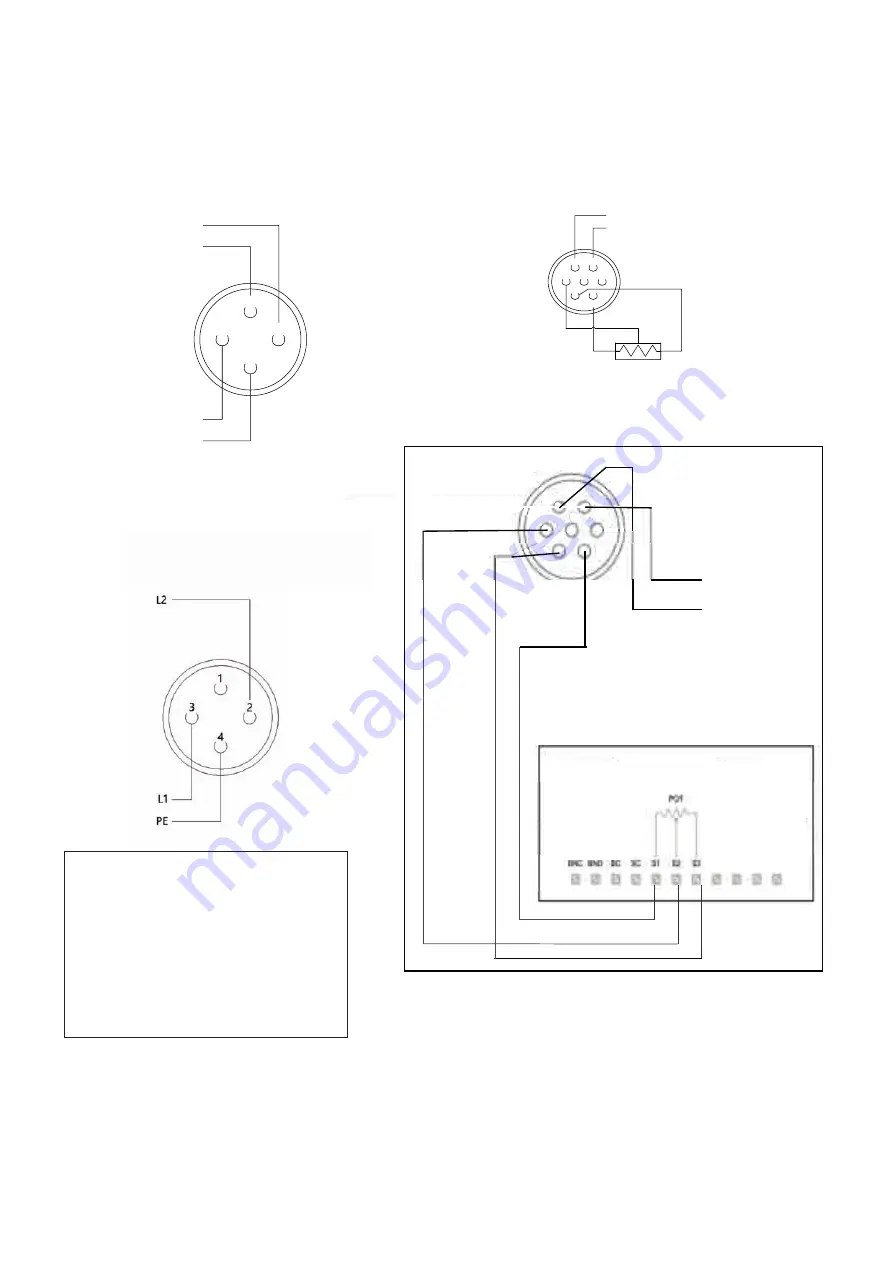
CONNETTORE ALIMENTAZIONE (TRIFASE)
L3
L2
L1
PE
CONNETTORE SEGNALE
IN/OUT CONNECTOR
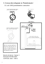
POTENTIOMETER CONTROL BOX
SCATOLA COMANDI POTENZIOMETRO
3
4
5
1
2
6
7
ANALOGIC IN
0-10 V
MODBUS B
MODBUS A
GND-I
POTENTIOMETER
POTENZIOMETRO
10V - I
10 Kohm
GND - I
MODBUS A
MODBUS B
ANALOGIC IN
0 - 10V
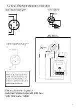
DETTAGLIO
CONNESSIONI
SUPPLY CONNECTOR (THREE-PHASE)
(SINGLE-PHASE)
CONNETTORE ALIMENTAZIONE (MONOFASE)
SUPPLY CONNECTOR (SINGLE-PHASE)
NOTA: È necessario portare in
un quadro ad altezza uomo, i cavi
A e B per il collegamento in
Modbus per azioni di
manutenzione e diagnostica
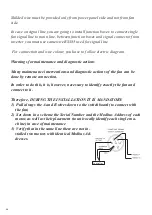
NB: It is necessary pull the A
and B wires down to the con-
trol box for the Modbus con-
nection, used for maintenance
and diagnostic actions.
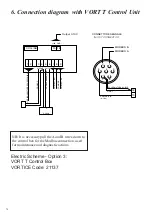
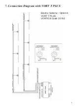
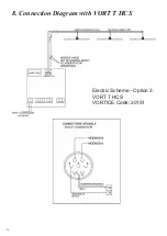
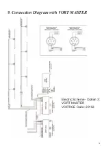
Electric Scheme - Option 1:
External Potentiometer
VORTICE code: 12832
5. Connection diagram to Potentiometer
5.1 cod. 12832 potentiometer connection
Summary of Contents for Nordik HVSL Super Blade 110 V Series
Page 1: ...NORDIK HVLS SUPER BLADE E SUPER BLADE 110 V Instruction booklet COD 5 571 084 939 23 07 2021 ...
Page 25: ...25 INVERTER MOTOR ELECTRONICS QUICK CONNECTORS ...
Page 28: ...28 Destratification Fan assembly ...
Page 56: ...56 Attachment 2 Electric connection ...
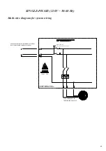
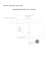
Page 67: ...67 Multi wire diagram for system wiring SINGLE PHASE 85 264V 50 60 Hz ...
Page 78: ......
Page 79: ......

