


72
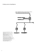
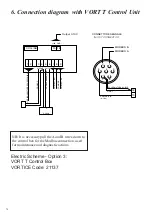
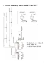
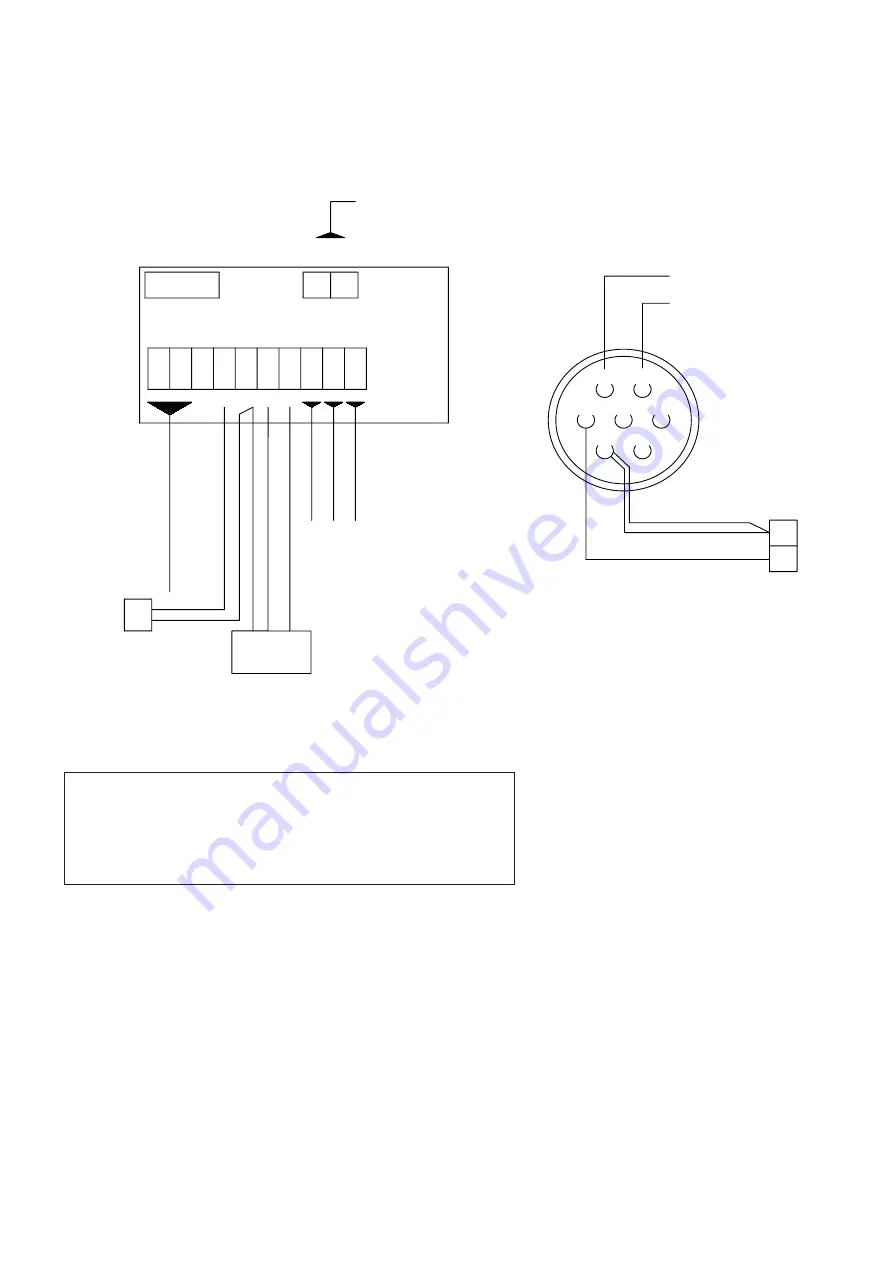
NB: It is necessary pull the A and B wires down to
the control box for the Modbus connection, used
for maintenance and diagnostic actions.
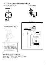
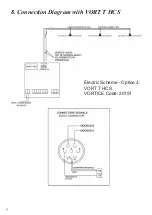
Electric Scheme - Option 3:
VORT T Control Box
VORTICE Code: 21137
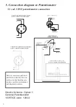
6. Connection diagram with VORT
T
Control Unit
3
4
5
1
2
6
7
ANALOGIC IN
(0-10 V)
MODBUS B
MODBUS A
IN/OUT CONNECTOR
CONNETTORE SEGNALE
GND-I
SCHERMATURA/SHIELD
19
18
18
19
XP-L4/AB
1
2
3
4
5
6
7
8
9
GND-
+10V
Output 0-10V
Pr2
Pr1+12V
GND-
CONT
ACT
NO
COMM
ON
CON
TA
CT NC
LINE 200-480V T
HRE
E-
PHA
SE
50
/60 H
z
PR
OB
E °C
PROB
E A
NEMO
ME
TER
- S +
4-20 mA
Summary of Contents for Nordik HVSL Super Blade 110 V Series
Page 1: ...NORDIK HVLS SUPER BLADE E SUPER BLADE 110 V Instruction booklet COD 5 571 084 939 23 07 2021 ...
Page 25: ...25 INVERTER MOTOR ELECTRONICS QUICK CONNECTORS ...
Page 28: ...28 Destratification Fan assembly ...
Page 56: ...56 Attachment 2 Electric connection ...
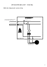
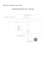
Page 67: ...67 Multi wire diagram for system wiring SINGLE PHASE 85 264V 50 60 Hz ...
Page 78: ......
Page 79: ......


