34
Operation
Motors
The unit is equipped with two brushless motors designed to ensure very low fuel consumption thanks to their very high
efficiency. They are driven by two centrifugal fans that extract spoiled energy, moist air from the utility rooms (kitchens,
bathrooms, laundry rooms, etc.) and introduce fresh outside air into inhabited rooms (living rooms, dining rooms,
bedrooms, etc.
Filters
Three G4 filters housed inside the delivery and extraction channels and on the bypass safeguard the device from impurities
contained in the exhausted air and prevent the introduction of polluted air into the serviced rooms.
Filter occlusion conditions can be monitored by removing the components in question from their housing.
Replace standard filter G4 housed in the fresh air inlet channel with optional filter M5 to ensure higher filtering capacities.
For Passivhaus compliant systems it will be necessary to replace the G4 filter housed in the fresh air intake channel and
in the bypass channel with F7 filters Cod.(21624,21626)
Bypass
This type of operation is activated automatically or can be selected by the user, and is useful to ventilate apartments without
heat transfer.
The opening of the bypass valve allows direct entry of outside air, preventing passage via the heat exchanger. The flow of
air exhausted from the house instead continues to pass through the exchanger.
The “bypass temperature” is the “desired temperature”, with respect to which the machine activates/deactivates the bypass.
The user can select the “bypass temperature” from temperatures ranging between 15°C and 30°C. If the user does not
select a temperature, the pre-set "bypass temperature" value is 18°C (default).
NOTE: Automatic “Bypass” operation is deactivated when:
- The outdoor air temperature is lower than 15°C
- The "No Frost" function is active
Automatic defrost
The “No frost” function activates automatically when the device detects outside air temperature that is too low for a certain
amount of time. When “No Frost” mode is active:
- The message “No Frost” will appear on the display
- The user cannot change Fan speed
- The “Programming” function is disabled
The main purpose of the "No Frost" function is to avoid damage to the device due to too low temperatures. In support of
this function, a pre-heater can be installed on the fresh air intake channel from the outside, and a post-heater on the fresh
air supply channel in the home.
When the message "Alarm!" and “Lock!” appears on the display: it rapresent a “no-frost timeout”. This means that “No-Frost”
procedure has proved insufficient and the appliance goes into protected mode for one hour, with the motors off, following
which it will restart automatically.
NOTE:
Re-activation of the device is automatic and does not require any operations by the user.
For Passivhaus compliant systems it will be necessary to install a preheater on the suction channel from the outside.
USB outlet
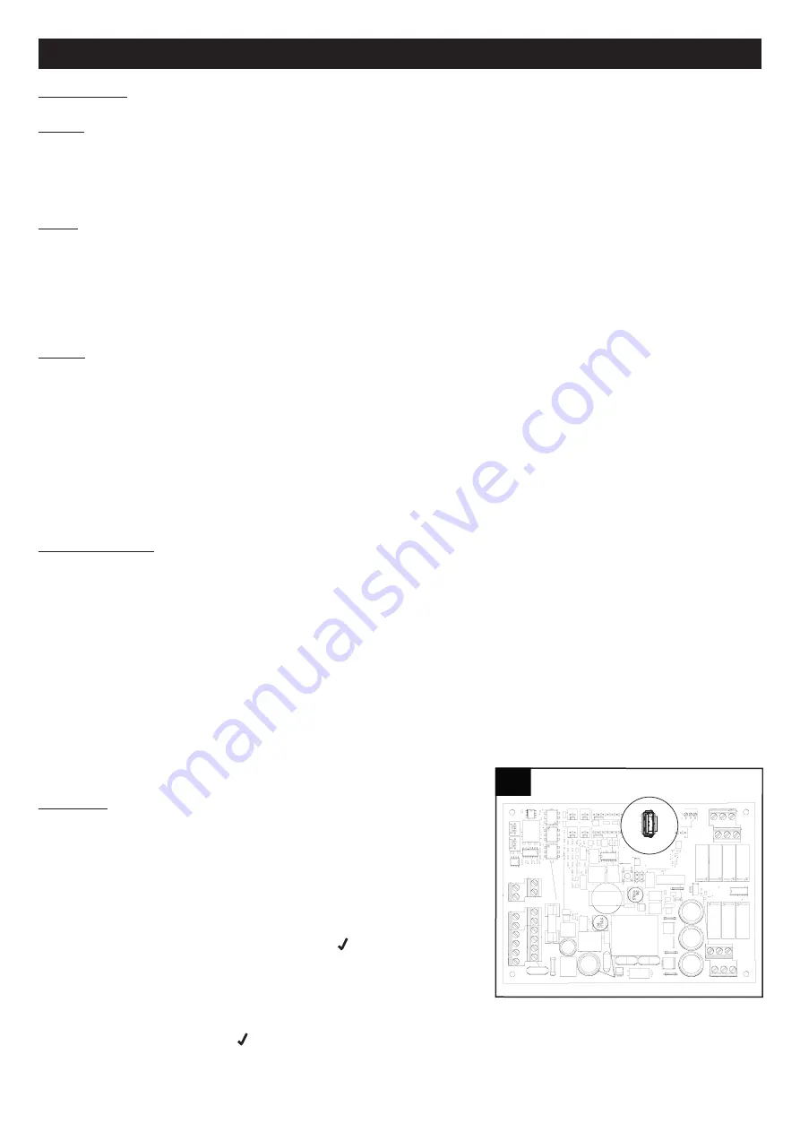
The USB outlet can be accessed on the circuit board (fig.15).
Procedure for software upgrade via USB (carried out by the Installer):
1. Copy the file “UECB_FW_UPGRADE.BIN” on a USB pen drive without
renaming it.
2. Disconnect the remote HMI, if installed.
3. turn off power to the machine.
4. Open the upper door and insert the USB pen drive in the machine.
5. Re-power the machine.
6. Wait about 30 sec – 1 minute: the LED symbol
will flash on the local
display of the machine.
7. The machine will resume normal operation at the end of the process.
8. Enter into the USE MENU with password 23 from the local HMI display
on the machine.
9. Change parameter “MBUD ID” so that it is different from 1 and different from that of the remote display: for example,
enter the number 2 and press
10. turn off voltage to the machine.
11. Connect the remote HMI.
ENGLISH
15
15
Summary of Contents for VORT HR 450 Avel D
Page 3: ...3 Vortice ZH 142 142 144 145 147 148 149 151 164...
Page 142: ...142 Vort HR 450 Avel D EC 85 Vortice 8 Vortice Vortice Vortice...
Page 143: ...143 45 C 3mm III M 220 240V 230V A 1 1 A...
Page 145: ...145 6 7 8 160mm 5 5a 5a 6 h 50 mm 60 mm 7 8...
Page 146: ...146 9 10 11 12 9 10 10 11 11 12 12...
Page 151: ...151 3 A B 1 2 T Ext T Int T Exh T Sup 3 4 OFF 1 2 3 Boost 5 6 A B 1 2 3 4 5 6...
Page 163: ...163 INFO S 0 9 6 6 M 0 9 6 4 CFG 6 4 MAIN MENU ALARM SETUP INFO...
Page 164: ...164 16 17 18 6 19 19A 17 17 18 18 16 16 19 19 A...
Page 165: ...165...
Page 180: ...180 Note...
Page 181: ...181 Note...
Page 182: ...182 Note...
Page 183: ...183 Note...


