Installation
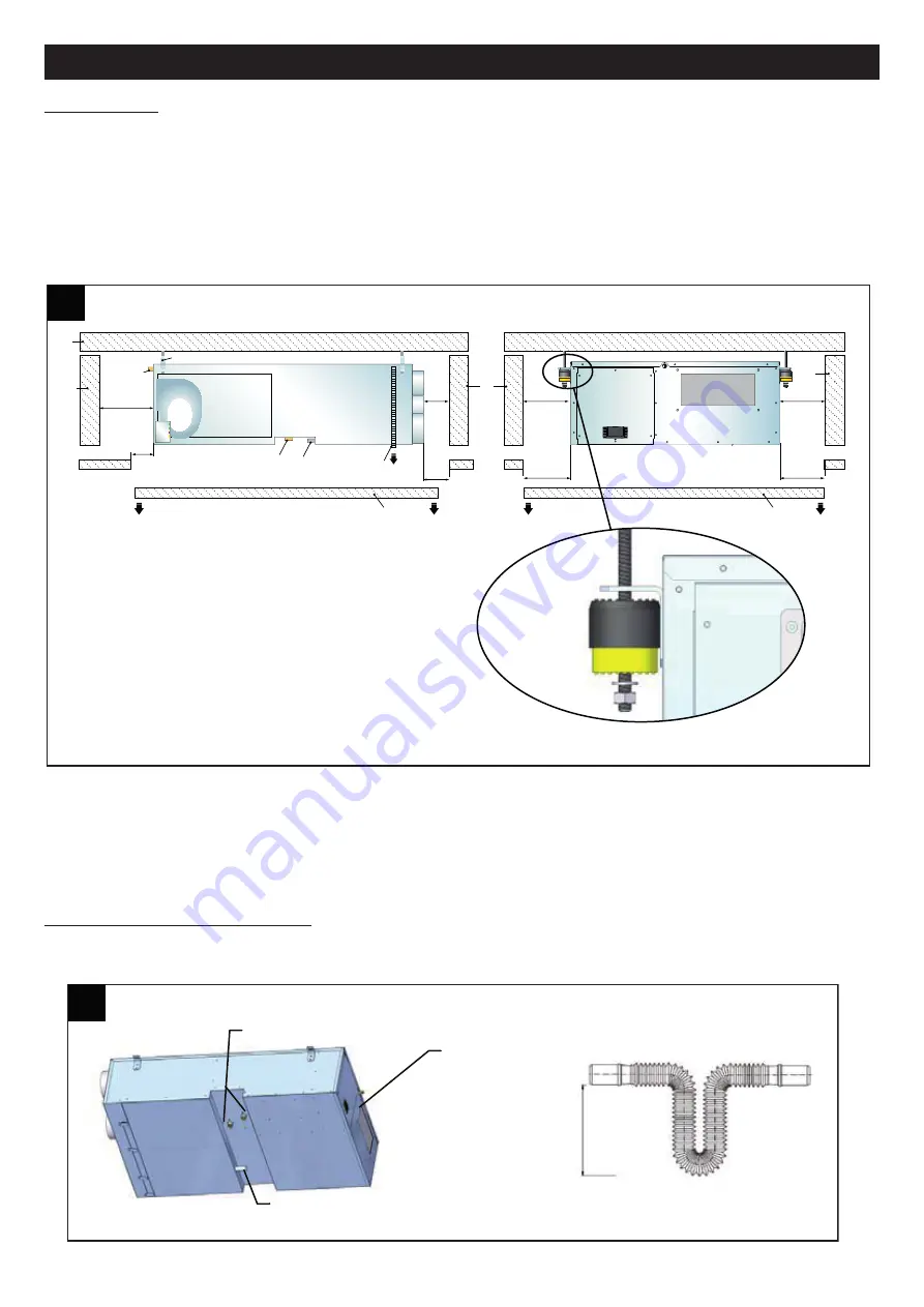
The appliance must be ceiling-mounted. The unit is hung on brackets;
the latter must be connected to the vibration dampers, which must be selected according to the type of structure to which
they are to be fixed.
You are advised to line the inside of the false ceiling with high-density sound-absorbing material, and create one or more
openings for removing and cleaning the air filters, checking the chiller circuit, and inspecting and maintaining the electrical
panel. (fig.7)
N:B.
The appliance must be installed so as to allow the ordinary and extraordinary maintenance. The warranty does not
cover the costs due to platforms and other lifting systems required by the warranty interventions.
N.B.
The installation site must be conform to Standards EN 378-1 and 378-3. When choosing the installation site must be
taken into consideration all risks arising from accidental loss of coolant.
N.B.
Make sure you create an opening in the false ceiling of sufficient size to allow the unit to be removed completely for
major servicing.
Connection to the condensate drain
The condensate drain on the appliance must be connected by means of a rubber hose fixed to the fitting with external
diameter of 20 mm located on the bottom panel, which also accommodates the water connections. (fig.8).
33
ENGLISH
7
7
500 mm
300 mm
300
mm
300 mm
300 mm
300 mm
300 mm
1
1
1
3
5
8
8
6
7
9
4
2
1
300
mm
8
8
≥
35
m
m
Collegamenti idraulici tipo gas maschio da 1/2”
Display
Collegamento scarico condensa diametro est. 20 mm
Key:
1. Ceiling and perimeter walls
2. Vibration-damping joint
3. Control card
4. Fan
5. Water connections
6. Condensate drain
7. Intake filter
8. Removable false ceiling
9. Bleed valve
Correct positioning for vibration-damping joint (not supplied)
½” male gas-type water connections
Display
Condensate drain connection with external diameter of 20 mm


