13
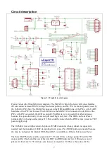
Close the hood. I prefer not to use the two locking screws because
the Wisp648 connector has no mating nuts, but feel free to use
them if you want.
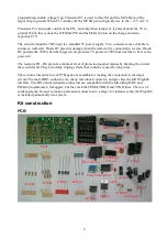
Strip a few millimeters from the other ends of the wires so they can
be inserted in a solderless breadboard.
Troubleshooting
Does the LED blink?
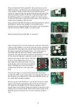
When power is applied to the Wisp648 (either by the target circuit, via the in-circuit programming
wires, or by a wall-wart), the red LED should blink three times. When the LED does not blink you
should check
•
the power supply, and
•
the Wisp648 circuit around the 16F648A chip in the programmer.
Is your power OK?
If you use a wall-wart to power the Wisp648, it must supply 9..18 V DC. An AC wall-wart might
work, but only for a target circuit that uses very little current (< 100 mA). If you use the target’s
5V to power the Wisp648, make sure that it is really 5.0 V, certainly not 4.5Vor 5.5V. In either
case you must put a 100nF capacitor over the power pins of the target PIC. A larger capacitor (22
uF or more, electrolytic is OK) must also be present, not more than 20 cm (sum of ground and 5V
wire or trace lengths) away from the target PIC.
Connector pin assignments
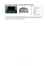
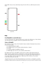
DB9 female: RS232
Note: if you use a cable between your PC and Wisp648 it must be a straight cable (not crossed).
Pins 2, 3 and 5 (ground, receive, transmit) need to be wired, the other wires can be wired or not.
Only three pins (GND, RxD, TxD) are used by the Wisp648, the other pins are wired to provide the
usual handshake feedback.
Wisp648 is designed to work with USB-to-serial converters. The performance (the time it takes to
program a chip) might be somewhat slower than with a ‘real’ serial port, but the functionality
should not be affected. It has been tested OK with converters based on Prolific and FTDI chips. If
you find a converter that does not work with a Wisp648 I am very interested.


