8
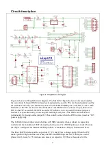
programming-enable voltage Vpp. Transistor T1 is used to (briefly) pull the MCLR pin of the
target chip to ground. When T1 switches off the MCLR pin will quickly rise to the ~ 13V on C9.
Transistor T2 can (under control of the PIC, and only when jumper J1 is placed) short the 5V to
ground. While this is done the 16F648A PIC and the MAX232 run on the charge stored in
capacitor C10.
The circuit around the 7805 (top) is a standard 5V power supply. Two connectors are available to
connect a wall-wart. Diode D7 prevents damage when the wall-wart is connected in reverse. Diode
D5 protects the 7805 when the target circuit provides 5V power (a 7805 does not like to be reverse-
powered).
The resistors R1 .. R6 provide a minimal level of protection against misuse by limiting the current
that could result. They also damp ringing effects that could be caused by long wires.
Three connectors and a row of PCB pads are available for making the connection to the target
circuit. The male DB15 connector is a cheap and robust connector, and provides the full Wisp648
interface. The RJ12 and pin-header connectors are compatible with the Microchip ICD2 and
PICkit2 programmers / debuggers, but they lack the TPGM, TRDX and TTXD lines. The row of
solder pads can be used to make a permanent connection to a target, for instance when the Wisp648
is installed permanently in a system.
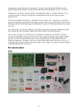
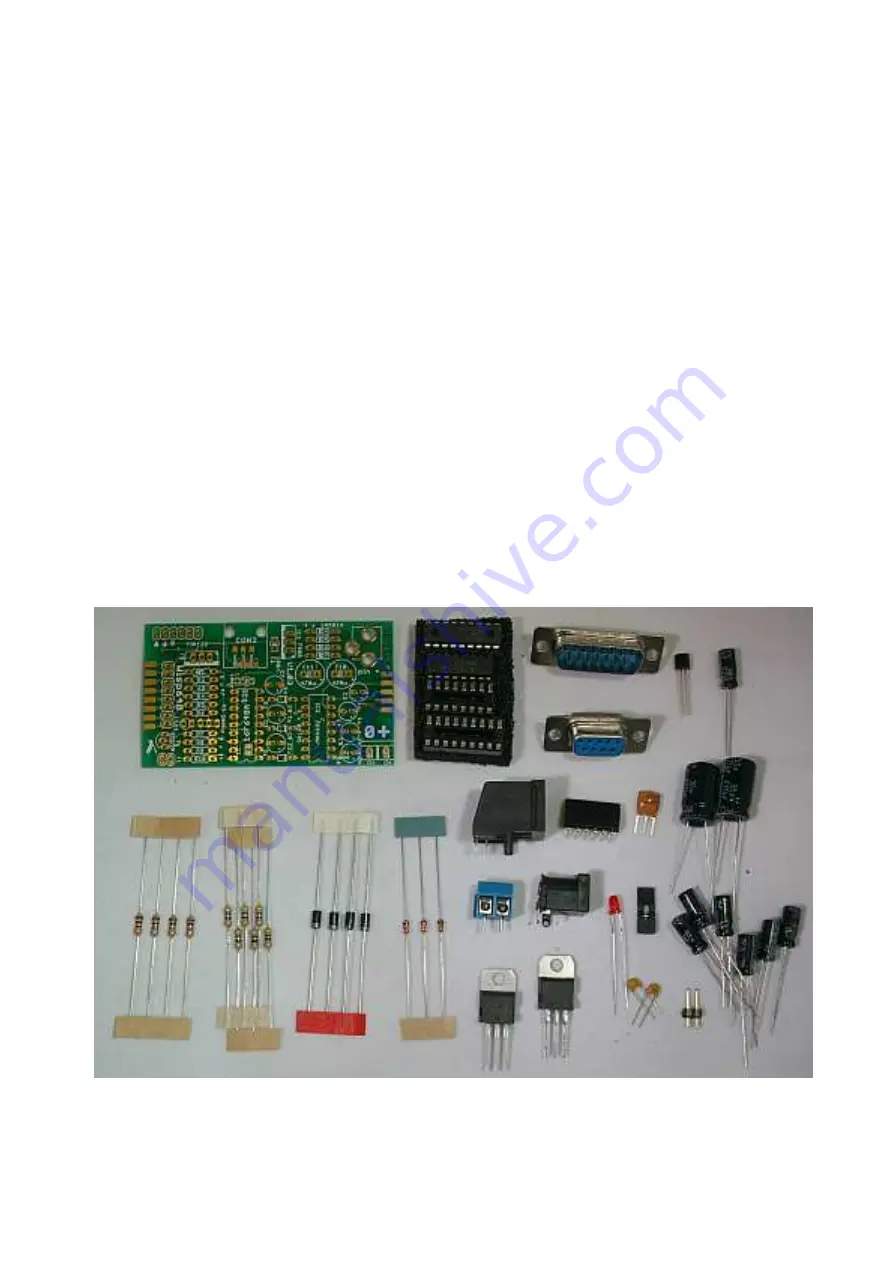
Kit construction
PCB
BAT85
1N5819
BC550
R 1k
Ω
R 47
Ω
DIP ICs and sockets
PCB
LED
C 22
µ
F
C 1
µ
F
C 470
µ
F
C 100nF
Pin header
jumper
IC 7805
TIP122
resonator
RJ connector
Power connectors
DB15 connector
DB9 connector
Right-angle
connector


