background image

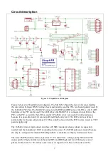
Place and solder the three BAT85 diodes. The (black) band on the 
diodes must be at the side of the white band in the PCB silkscreen 
(white print on the PCB). Trim the wires. 


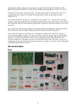
Place and solder the four 1k

 (brown – black – red) resistors. 

Resistors are not polar, so it does not matter in which direction they 
are placed, but for aesthetic purposes it makes sense to have them 
all point in the same direction. Trim the wires.  


Place and solder the six 47 

 (yellow - purple – black) resistors. 

Resistors are not polar, so it does not matter in which direction they 
are placed, but for aesthetic purposes it makes sense to have them 
all point in the same direction. Trim the wires. 


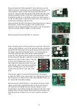
Place and solder the four 1N5819 diodes. The white band on the 
diodes must be at the side of the white band in the PCB silkscreen 
(white print on the PCB). Trim the wires. 


Place and solder the right-angle pin-header connector. For a good 
connection it is recommended to solder both top and bottom sides. 


Place and solder the two 100 nF capacitors. Trim the wires. 


Place and solder the two PCB sockets. The sockets have a notch at 
one end, which should be above the notch in the silkscreen (white 
print). 


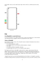
Place and solder the DB9 (female) and DB15 (male) connectors. 
Shifting the connectors over the PCB edge might require some 
force. There is only one way the two connectors can be places with 
each solder cup over a copper field on the PCB. 


Summary of Contents for Wisp648

Page 1: ...ts target circuit There is no need to extract the chip from its circuit put it in a programmer and put it back in the circuit after programming Instead you make a connection a few wires between the pr...

Page 2: ...PIC pin functions not the pin numbers because the numbers of the pins used vary from chip to chip The table below works for most DIL chips but the chip s datasheet is the final authority Especially th...

Page 3: ...d PGD pins and the rest of the target circuit is connected via a two resistors of 1k or higher The programming mode used by Wisp648 is called HVP for High Voltage Programming because a high voltage on...

Page 4: ...onnector which is commonly used for wall warts The centre pin is positive which seems to be the most common polarity Unfortunately about 10 other connectors and 1 other polarity are also commonly used...

Page 5: ...uivalent chip is the standard way to interface between the TTL signals and the RS232 signals But some dirt cheap PIC circuits interface the PIC pins directly to the RS232 signals This violates all des...

Page 6: ...6F648A chip Remove the 16F648A chip from the Wisp648 Use that second programmer to program the new firmware into the chip Put the 16F648A chip back into the Wisp648 If you don t have a second programm...

Page 7: ...t is open drain only it can not pull itself high only low The LED can be activated permanently by closing solder jumper J2 This could be done when the PCB is mis used as 7805 power supply only The 16F...

Page 8: ...6 provide a minimal level of protection against misuse by limiting the current that could result They also damp ringing effects that could be caused by long wires Three connectors and a row of PCB pad...

Page 9: ...nse to have them all point in the same direction Trim the wires Place and solder the four 1N5819 diodes The white band on the diodes must be at the side of the white band in the PCB silkscreen white p...

Page 10: ...ader The latest version of the PCB uses a three pin header Place and solder the screw connector Place and solder the centre pin power connector I find it convenient to bend two of the pins before sold...

Page 11: ...nserted in the hole with the square copper pad and marked with a Or all electrolytic capacitors must have their white bands towards the DB15 connector The capacitor nearest to the four diodes has a ve...

Page 12: ...over the wires and the solder cups The picture shows white tubes but the color can vary Apply heat to shrink the heat shrink The fumes from the heat shrink are not healthy so do this in the open air A...

Page 13: ...ake sure that it is really 5 0 V certainly not 4 5Vor 5 5V In either case you must put a 100nF capacitor over the power pins of the target PIC A larger capacitor 22 uF or more electrolytic is OK must...

Page 14: ...in connector and screw connector wall wart The Wisp648 has two power connectors you can use the one you prefer The black 2 5 mm centre pin connector is convenient and matches the connector often found...

Page 15: ...ound 4 PGD 5 PGC 6 Not connected The Wisp648 has a PICkit2 compatible pin header connector You can use this connector connect to a target board that has a PICkit2 compatible pin header connector The t...

Page 16: ...3 26 PGM 4 25 5 24 PGM 6 23 7 22 GND 8 21 9 20 VCC 10 19 GND 11 18 12 17 13 16 14 15 28 pin skinny DIP 1 18 2 17 3 16 MCLR 4 15 GND 5 14 VCC 6 13 PGD 7 12 PGC 8 11 PGM 9 10 PGM 18 pin DIP The picture...

Page 17: ...No build in 7805 power supply No build in TIP122 circuit could be added externally as dongle No LED No ICD2 and PICkit2 compatible connectors MCLR Vpp was forced to 5V via diodes and 1k resistor The W...

Page 18: ...protection is a feature that the author of a program can enable if he chooses to do so If he did you are out of luck and you probably have no business copying that chip There are companies that will r...

Page 19: ...ftware is modified to accept the identification Wisp648 Programming 18F fuses does not work Some PIC fuses settings in particular the enabling of the PLL in 18F chips require a power up to take effect...

Page 20: ...it replaced by a corrected version 4 You could repair the PCB This requires cutting two traces and soldering one wire The pictures below show the steps This is probably best done after the board is a...

Page 21: ...cant current MCLR Master CLear and Reset The reset pin available on most PIC chips This pin also serves to enable the PIC programming mode when the pin is quickly raised from 0V to the Vpp level On mo...

Page 22: ...hip Vss Name for the negative or ground 0V power supply connection of an IC The dd part might in analogy with Vcc be derived from common source WISP Wouter s In System PIC Programmer My first PIC prog...

Page 23: ...tight fit Aat Koch 2007 12 15 FAQ added Wisp648 identifies itself as Wisp628 Fris Kieftenbelt DB15 connector on the PCB must be male Rikard Bosnjakovic 18F PLL fuse FAQ added some textual refinements...

Reviews: