XR3D-6 Maintenance & Troubleshooting
EM-XR3D-6-001-EN.D
6-9
©2011 VOTI Inc.
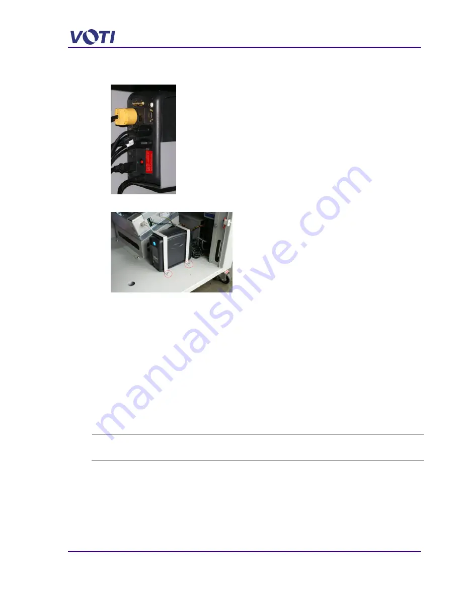
Note the location of the plugs. For example, the plugs on the right are for the Source and the
Control Unit. The left side is for the Computer, Monitor(s), and Power Distribution Unit.
5. Unbolt the one side of the UPS bracket using a 10mm socket wrench.
6. Slide the unit out of the bracket.
7. Place a new UPS in the scanner and re-attach all the plugs.
8. Secure the UPS bracket using the two (2) retaining bolts.
9. Plug the scanner power cable to the wall receptacle.
10. Press the UPS Power button to ensure the UPS turns on and the UPS LCD Display
illuminates.
11. Replace and secure the front access panel.
6.7 Remove and Replace the Emergency Stop Switch
There is an Emergency Stop switch on each end of the XR3D-6 scanner. The Emergency Stop
switch comes in a kit which must be assembled before installing on the XR3D.
Tools:
Screwdriver with Security Chuck
Phillips (or Flathead) screwdriver 3-6mm
To replace the switch, proceed as follows:
1. Unplug the scanner power cable from the wall receptacle.
2. Using a screwdriver with the security chuck, remove the (2 or 4) security screws (M6 x 25
SS machine screw with a 6 point security head) on the base front access panel.
3. Turn off the UPS by pressing the power button.
Summary of Contents for XR3D-6
Page 2: ...XR3D 6 Maintenance Troubleshooting ii EM XR3D 6 001 EN D 2011 VOTI Inc...
Page 6: ......
Page 20: ...XR3D 6 Maintenance Troubleshooting 2 8 EM XR3D 6 001 EN D 2011 VOTI Inc...
Page 32: ...XR3D 6 Maintenance Troubleshooting 3 12 EM XR3D 6 001 EN D 2011 VOTI Inc...
Page 48: ...XR3D 6 Maintenance Troubleshooting 3 28 EM XR3D 6 001 EN D 2011 VOTI Inc...
Page 52: ...XR3D 6 Maintenance Troubleshooting 4 4 EM XR3D 6 001 EN D 2011 VOTI Inc...


