background image

© 2020 Van Putten Instruments BV | MAN-VP-LOGR-UK | Revision: 2001 | Date: 01-10-2020

10

13 88

I RMS (5000 -> 500.0 AAC)

13 88

I RMS (5000 -> 50.00Hz)

73 CB

CRC

6

Configuration

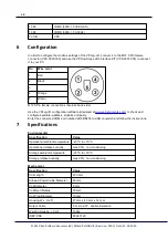
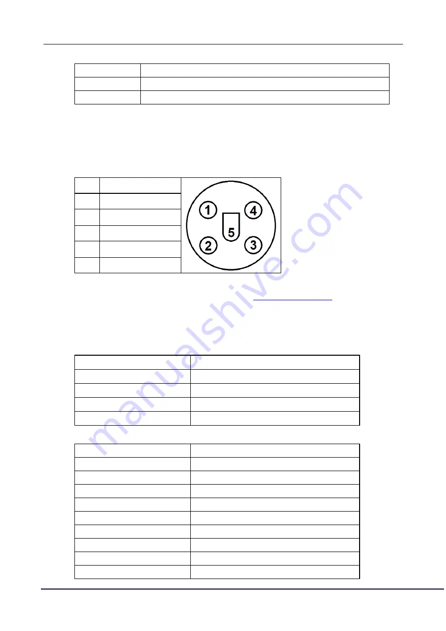
In order to configure the modbus settings of the VPLog-i-R, connect it to the M12 5 Pin female
connector (VPA.0000.300) and use the VPFlowScope JB5 interface KIT (VPA.5001.205) to connect
it to your PC. 

Pin

Wire color

1

Red

2

Black

3

-

4

Orange

5

Brown

M12 5 Pin female connections (internal, back side)

Use the VPLog-i-R configuration software (download at 

www.vpinstruments.com

) to check and

configure baudrate, address, stopbits and parity.
Enter the connected COM port number (JB5 RS458 to USB converter) and follow the instructions. 

7

Specifications

Environmental

Specification

Value

Operational ambient temperature

-20 ºC to +70 ºC

Operational relative humidity

max 95%, non-condensing

Storage ambient temperature

-20 ºC to +70 ºC

Storage relative humidity 

max 95%, non-condensing

Mechanical

Specification

Value

Coil Length 

250 mm

Allowed Power Cable Diameter

65 mm

Coil Diameter

6 mm

Coil Bend Radius

30 mm

Coil Plug Diameter

12 mm

Housing W x H x D 

27 mm x 40 mm x 14 mm

Output Cable

5 m UL-LiYY, double insulation

Weight (H Coil)

150gr

IDEP/CN8

8504.3129

Summary of Contents for VPLog-i-R

Page 1: ...VPLog i R VPINSTRUMENTS COM User manual 2020 Van Putten Instruments BV MAN VP LOGR UK 2001 Date 01 10 2020 ...

Page 2: ...While every precaution has been taken in the preparation of this document the publisher and the author assume no responsibility for errors or omissions or for damages resulting from the use of information contained in this document or from the use of programs and source code that may accompany it In no event shall the publisher and the author be liable for any loss of profit or any other commercia...

Page 3: ...3 Table of Contents 1 Introduction 4 2 Safety Regulations 5 3 Instrument Description 6 4 Installation 7 5 Connection 8 6 Configuration 10 7 Specifications 10 ...

Page 4: ...al and the functional specifications of the VPLog i R current sensor Glossary AC Alternating current CF Crest Factor Peek_current RMS_current DC Direct current GND Ground Hz Hertz IDEP CN8 Combined Nomenclature code mA milli Ampère ppm Parts pro million 1ppm 0 0001 1 1000000 PWR power true RMS true Root Mean Square Urms sqrt mean U ...

Page 5: ...mation that is extraneous to the immediate subject of the text A note will be preceded by the caption NOTE and the detail will be in italics All warnings cautions and notes will precede the relevant sections of the text General safety regulations WARNING THIS DEVICE IS NOT DESIGNED FOR AND THEREFORE NOT INTENDED FOR USE IN ANY ENVIRONMENT WHERE HUMAN LIFE DEPENDS DIRECTLY ON THE USE OF PROVEN RELI...

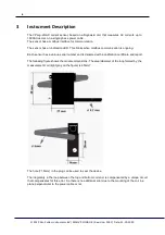
Page 6: ...on is ongoing Each sensor has a unique serial number and is delivered with a calibration certificate and report The following figure shows the module dimensions The area diameter of the loop formed by the measurement coil light gray on the figure is 65mm The hole 1 5mm in the plug can be used to seal the device The irregularity in the loop between the top and bottom coil end is compensated by a un...

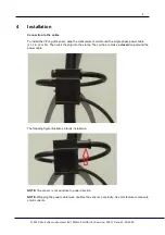
Page 7: ...nt coil around the single phase power cable L1 L2 L3 or N Then click the plug into the clamp The coil has to make a closed loop around the power cable The following figure illustrates a faulty installation NOTE The sensor is not sensitive to power direction NOTE Wrapping the power cable twice doubles the sensor s sensitivity Use this feature to measure small currents ...

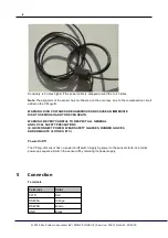
Page 8: ...OLTAGES ARE HAZARDOUS AND CAUSE AN IMMEDIATE RISK TO SERIOUS INJURY OR EVEN DEATH WARNING BE VERY CAREFUL TO RESPECT ALL GENERAL AND LOCAL SAFETY PRECAUTIONS E G DISCONNECT POWER WEAR SAFETY GLASSES RUBBER GLOVES AND ADEQUATE CLOTHES ETC Power On Off The VPLog i R sensor has no power on off switch Applying power to the sensor starts its internal power up sequence Switch the sensor off by removing ...

Page 9: ...ng the 16 bit values modbus supports the commands Read Holding Registers 0x03 When addressing registers the command contains the address minus 1 for instance registers 1 3 are addressed as 0 2 The VPLog i R also supports the modbus scan protocol This allows to change the modbus settings and to request extra information from the module Modbus example Example 1 The following example contains a reque...

Page 10: ...ad at www vpinstruments com to check and configure baudrate address stopbits and parity Enter the connected COM port number JB5 RS458 to USB converter and follow the instructions 7 Specifications Environmental Specification Value Operational ambient temperature 20 ºC to 70 ºC Operational relative humidity max 95 non condensing Storage ambient temperature 20 ºC to 70 ºC Storage relative humidity ma...

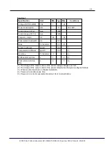
Page 11: ...th Hz 720 Noise full scale 0 2 0 5 Supply coefficient ppm V 160 1 Temperature coefficient ppm C 100 2 Accuracy full scale 1 1 3 Modbus start up time s 1 2 4 Measurement start up time s 2 3 5 1 The change of the output current if the sensor voltage changes one Volt 2 The change of the output current if the sensor temperature changes one degree Celsius 3 When mounted as shown in chapter Installation...

Page 12: ... 2020 Van Putten Instruments BV MAN VP LOGR UK Revision 2001 Date 01 10 2020 12 ...

Page 13: ...13 Notes 2020 Van Putten Instruments BV MAN VP LOGR UK Revision 2001 Date 01 10 2020 ...

Page 14: ...VPLog i R 14 Notes 2020 Van Putten Instruments BV MAN VP LOGR UK Revision 2001 Date 01 10 2020 ...

Page 15: ...easy insight into energy flows MAN VP LOGR UK 2001 Date 01 10 2020 Buitenwatersloot 335 2614 GS Delft The Netherlands info vpinstruments com www vpinstruments com VPInstruments ...

Reviews: