background image

38

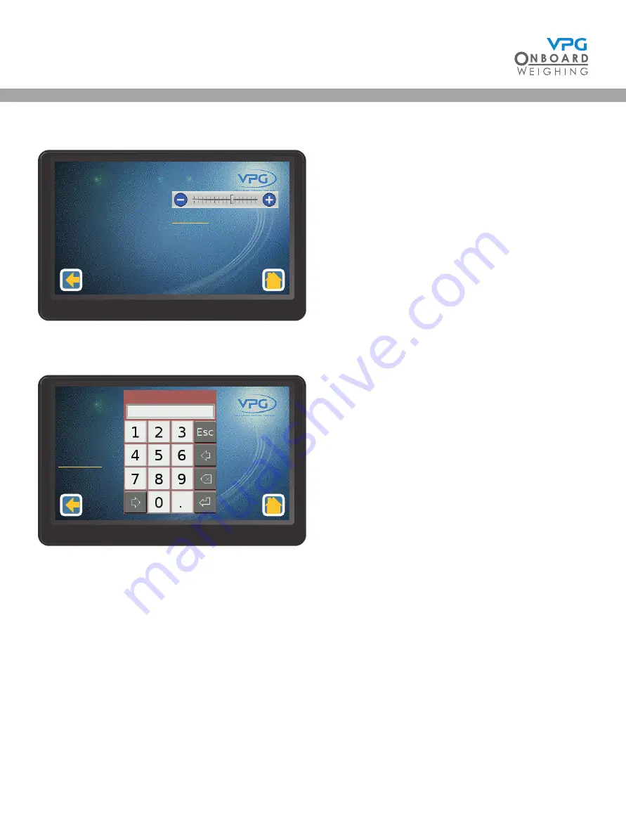
Sliders:

Tap the + or - icons to adjust the value up or down.

Keypad:

Tap to enter the numerical value and tap the return button to set the value

Brightness

Language

English

Display Configuration

1/2

Axle 1 Span Weight
Axle 2 Span Weight
Do Span

1700
2000

Axle Calibration

1/1

Cal. Span Weight

VanWeigh

®

Summary of Contents for VanWeigh

Page 1: ...vpgonboard com VanWeigh Installation Setup and Calibration Manual ...

Page 2: ...2 VanWeigh ...

Page 3: ...on of the weighing equipment including but not limited to any misapplication or misinterpretation of the installation information contained herein Strict observance of these guidelines should help to ensure accurate weight measurement and enable safe operation of the vehicle Failure of our on board vehicle weighing equipment due to poor installation workmanship or incorrectly installed elements re...

Page 4: ... Unit Overview 34 Display unit operation 35 Home Page 35 How to navigate the system 36 Editing Values 37 Configuration 39 The configuration menu 40 Login 41 Vehicle configuration 42 How to configure the junction box 43 How to configure the alarms 47 Weighing the Vehicle 48 How to calibrate the junction box 51 How to configure the display 54 How to configure a serial output 56 How to configure the ...

Page 5: ...5 VanWeigh ...

Page 6: ...be configured to use either type of transducer and any combination of the two About this document Any display screenshots used in this document are intended as an illustration of the function being described As such any specific detail or settings shown will differ from one installation to another The documentation uses the following conventions Important These are important notes and appear insid...

Page 7: ... identified and that location should then be prepared for the transducer to be attached See How to install a steel axle transducer on page 27 VanWeigh axle transducer orientation Axle transducers must be mounted to the vehicle in the correct orientation See How to install a steel axle transducer on page 27 Accurate recording of sensor serial numbers in their sensor positions It is recommended that...

Page 8: ...8 VanWeigh ...

Page 9: ...9 Installation VanWeigh ...

Page 10: ...VanWeigh display unit is supplied for the vehicle Part No 551430 Display Mount A single display mount is supplied for the display unit Part No 551430 MOUNT Axle Transducer A single cable with a connector at one end and the axle transducer at the other This is supplied for steel axle suspension systems A single transducer is supplied for each transducer position See Sensor installation positions on...

Page 11: ...ied for air suspension systems A single transducer is supplied for each transducer position See Sensor installation positions on page 23 Part No 996210C For air pipe outside diameter 8mm 10mm Part No 542549 Air sensor only Internal Domain Cable with Air Transducer Fitting A single transducer cable is supplied for each air transducer position See Sensor installation positions on page 23 Part No DRG...

Page 12: ...r and 3 male internal domain cable connectors Part No DRG 106898 External Internal Domain Junction Box Cable 2 way A single external domain output cable is supplied for each junction box The cable is identified by the brown junction box connector at one end and at the other end one external domain cable connector and one male internal domain cable connector Part No DRG 106897 VanWeigh ...

Page 13: ...e external domain cable connector at one end and the display connector at the other Part No DRG 106143 Cable Protector and Cable Ties Cable protector is supplied and can be cut as required Cable ties are also supplied Part No 493459 Surface Cleaning Wipes Part No 995627 Double Sided Bonding Tape Part No 995614 VanWeigh ...

Page 14: ...e the following tools before starting an installation Tool Check Screwdriver set Hex driver set Torx driver set Socket set Multimeter Side cutters Drill set G Clamp Spanner set including 18 mm and 24 mm Air pipe cutters VanWeigh ...

Page 15: ...as been installed configured and calibrated The display unit is connected to the junction box via the external domain cable The junction box is installed on the chassis of the vehicle and is connected to all four sensors on the vehicle The sensors and junction box form the internal domain The sensors send information back to the junction box The junction box then transmits information back to the ...

Page 16: ...uspension systems and the cab of the vehicle The sensor and display unit cables must be able to reach the junction box Sensor installation The type of sensors you install will depend on the suspension systems in operation on the vehicle Air pressure transducers are installed on air suspension systems Axle transducers are installed on steel axle suspension systems The sensors must be installed in a...

Page 17: ...elation to the vehicle These are two example schematics but a variety of configurations may be used Leaf Spring Air Spring Truck Air System Truck Air System VanWeigh Display unit Junction Box and Axle Transducers Suspension Air Bags Air Transducers Leaf Spring Leaf Spring VanWeigh Display unit Junction Box and Axle Transducers VanWeigh ...

Page 18: ... vehicle 2 Route the external domain cable on the display unit cable from the the location of the display unit in the cab to the location for the junction box Avoid running cables on or near sharp objects Keep cables away from hot components such as exhausts and engines Use cable protector to protect the cable at positions where it may be exposed to damage It is recommended that you follow existin...

Page 19: ... WILL TURN ON BY THE IGNITION KEY AND TURN OFF BY AUTO POWER OFF CONFIGURATION OPTION 2 BROWN WHITE BLUE THE DISPLAY WILL TURN ON OFF BY THE IGNITION KEY OR THE STAND BY ICON WHEN THE IGNITION IS ON 2 3 2 4 5 4 5 3 WD7216 DRAWING No POWER SUPPLY WIRING DETA TITLE G C THIRD ANGLE PROJ MATERIAL ALL DIMS IN MM UNLESS OTHERWISE STATED DRAWN No OFF VanWeigh 2 PROJECT NAME NTS SCALE 24 06 19 DATE SURFAC...

Page 20: ...able sockets must point to the rear of the vehicle The VanWeigh system will not provide the correct measurements if the junction box is not mounted with the cable sockets pointing to the rear of the vehicle Use existing holes on the chassis to mount the junction box if possible Drill holes appropriate to the size and length of the mounting screws if existing holes are not suitable Use 2 X 1 4 or M...

Page 21: ...wn tab This is the connection for the fourth sensor and external domain cable Sensor information is transmitted from the fourth sensor to the junction box via this port Information is transmitted to the display unit from this port 1 Connect the three way sensor input cable to the green port on the junction box 2 Connect the two way sensor input and external domain connector cable to the brown port...

Page 22: ...transducer This type of sensor can be mounted on steel axle suspension systems This includes Front strut type suspension Single axle leaf springs Air pressure transducer This type of sensor can be mounted on air suspension systems Air pressure transducers can only be used on air suspension systems that are self levelling VanWeigh ...

Page 23: ...nsor which you install its position number and where it is installed on the vehicle It is recommended that you use the system configuration table to record this information and refer to it when you are configuring the system See System configuration table on page 68 Serial xxxx Position 2 Front right axle Serial xxxx Position 1 Front left axle Serial xxxx Position 4 Rear right axle Serial xxxx Pos...

Page 24: ...isk of damage from any part on the vehicle throughout the full range of movement of the strut The sensor cable can be routed to the junction box without risk of damage from any moving parts and allowing for the full range of movement of the transducer on the strut When mounting the sensor ensure it is in the correct orientation with the groove at the top See How to install a steel axle transducer ...

Page 25: ...ar of the spring with the cable running away from the axle The transducer is not at risk of damage from any part on the vehicle throughout the full range of movement of the spring The cable can be routed to the junction box without risk of damage from any moving parts and allowing for the full range of movement of the transducer on the spring When mounting the sensor ensure it is in the correct or...

Page 26: ...en the self levelling valve and the air bellows The air transducer can be supported without risk of damage from any moving parts The cable can be routed to the junction box without risk of damage from any moving parts System Pressure Air Reservoir Self Levelling Valve Air Pressure Transducer Suspension Bellows VanWeigh ...

Page 27: ...surface is at an appropriate temperature The ideal temperature of the mounting surface is 70 F 21 C If required warm the spring with a hot air gun before bonding the transducer It is not recommended to apply the bonding tape at temperatures below 60 F 15 C 3 Warm the bonding tape in your hands and apply it to the appropriate side of the sensor The sensor must always be mounted with the face adjace...

Page 28: ...ote of the serial number of the sensor and the location on the vehicle where it is installed 6 Make a note of the serial number of the sensor the position it is located on the vehicle and the direction it is facing e g SN xxxx position 1 front left sensor facing forward The internal domain cable is attached to the rear of the transducer The opposite face is used to indicate which direction the sen...

Page 29: ...sducer must be installed on each air circuit For example two air circuits one with a ride height control valve to control the bellows on the left side and one with a ride height control valve to control the bellows on the right would require two air pressure transducers one for the circuit on the left side of the truck and one on the right Ensure that you select the appropriate position for the se...

Page 30: ...e 18 mm and 24 mm spanners to tighten iv Remove the cap from the sensor v Connect the fitting and sensor to the stem of the air pressure T connector Push fit until you hear two clicks to lock the sensor and T connector together vi Connect the air pipe fittings to each side of the tee on the T connector Push fit until you hear two clicks to lock the air pipe fitting and T connector together ii iv v...

Page 31: ...rapped around the air transducer connector and a little way up the cable to provide protection 4 Cut the air pipe at the appropriate position 5 Cut approximateley 1 of pipe off the cut end of the air pipe 6 Clean any dirt from the ends of the air pipe 7 Connect the air pipe to each side of the air pressure transducer Push fit until you hear one click to lock the pipe into the pipe fittings 8 Conne...

Page 32: ... cable ties to secure any excess cable to the chassis of the vehicle Use cable protector to protect the cable at positions where it may be exposed to damage Ensure that you make a note of the serial number of the sensor and the location on the vehicle where it is installed 10 Make a note of the serial number of the sensor and the position it is located on the vehicle e g SN xxxx rear left air circ...

Page 33: ...33 System Overview VanWeigh ...

Page 34: ...e the junction box on page 51 The display unit will show a message to indicate the current stage of the configuration and calibration process Axles Sensors Zero Span This message indicates that a junction box has been detected but the axles and sensors have not been configured and the zero and span calibrations have not been done Zero Span This message indicates that a junction box has been detect...

Page 35: ...be applied The weight of the vehicle that is currently over the front axle and its percentage of the maximum weight that can be applied to that axle The weight of the vehicle that is currently over the rear axle and its percentage of the maximum weight that can be applied to that axle Swipe left or right for alternative displays of this information The last screen that is shown when you power down...

Page 36: ... are five home page menu options USB System info USB Configuration USB Diagnostics USB USB USB Standby Tap to switch the display unit off Tap a menu option to open its associated page USB 64 2240 81 1460 37 780 kg Vehicle Display Junction Box Count Messages 1 0 System Info 1 1 VanWeigh ...

Page 37: ...nother menu or an editable value Tap to access Tap to save any changes Editing Values There are three methods for editing the values in the system The appropriate method is displayed when an editable value is tapped Selectable options Tap the or arrow to cycle through the options Tap the green tick to select the displayed option xxxx 1 2 Junction Box Orientation Axles Sensors 1 1 Disabled 2 3 Junc...

Page 38: ...up or down Keypad Tap to enter the numerical value and tap the return button to set the value Brightness Language English Display Configuration 1 2 Axle 1 Span Weight Axle 2 Span Weight Do Span 1700 2000 Axle Calibration 1 1 Cal Span Weight VanWeigh ...

Page 39: ...39 Configuration 2240 VanWeigh ...

Page 40: ...n is complete Display Use this menu to configure the brightness language volume date time and power off timer settings of the display unit System Config Use this menu to configure any additional features such as a serial scoreboard output Weighing Config Use this menu to configure the weighing units and how the weight values are displayed PIN Management Use this menu to edit the PIN numbers that a...

Page 41: ...stem 1 Tap the configuration icon in the home page to open the configuration menu 2 Tap login to display the keypad 3 Tap to enter the Engineer PIN number 4 Tap the return icon Only VPG approved installers can have engineer PIN Login Please Enter PIN VanWeigh ...

Page 42: ...le configuration menu The vehicle configuration is a step by step process that allows you to configure the junction box and alarms and finally calibrate the system The vehicle configuration menu displays the configuration settings for the junction box on the vehicle Junction Box JBox Config Alarms Calibration 1 1 Vehicle Configuration 1 1 VanWeigh ...

Page 43: ...ermined by the direction the top face of the box is facing For example Up down left side or right side of the vehicle Please see How to install the junction box on page 20 for further details 4 Tap the Axles numerical value 5 Select the number of axles that are monitored by the junction box The junction box is able to connect to 4 sensors on the vehicle over 2 axles Junction Box Orientation Axles ...

Page 44: ...t axle transducers are located on a single leaf spring axle This type of configuration will usually have 2 sensors on each axle one for each side of the vehicle 10 Repeat steps 8 and 9 to configure each axle for the junction box 11 Tap the back icon A message box appears saying Send Axle Map to Jbox 12 Tap yes to update 13 Tap the back icon to return to junction box setup page Axle Number Type Sen...

Page 45: ...position if the sensors have been connected to the corresponding labelled connection cable to the junction box E g sensor on front left wheel connected to FLH label connection wire will be Sensor position 1 17 Tap the Direction value to set the direction for sensor Select Forwards if the sensor is facing the front of the vehicle Select Backwards if the sensor is facing the rear of the vehicle Sele...

Page 46: ...le is stationary Set to off to turn the jitter filter off Set to 1 2 or 3 to apply a stabilising filter to the data that is displayed on the home page This should be set to the required level after the calibration is complete 23 Tap the back icon If the jitter filter has been changed a message box will appear saying Settings have changed Send to Jbox Yes Discard changes No Tap Yes to update Juncti...

Page 47: ...ap the Gross Alarm value to set the value that will trigger the alarm when the total weight on the vehicle exceeds the maximum allowable weight 3 Tap the Enable value to enable or disable the gross alarm 4 Tap the Save icon 5 Swipe up and tap Axles to open the axle alarm config menu Junction Box Gross Alarm Enable 1 1 3500 kg Enabled JBox Alarms Config 1 2 Junction Box Axles 1 1 2 JBox Alarms Conf...

Page 48: ... vehicle weight GVW before you calibrate the system Two sets of vehicle measurements must be taken Zero weights This is the weight measurement of each axle when the vehicle is empty Span weights This is the weight measurements of each axle when the total weight of the vehicle is as close to GVW as possible The zero weights calibration data should be entered into the display unit when the vehicle i...

Page 49: ...hich are not being weighed 2 Add together the weight measurements for both sides of the axle to calculate the current weight of the axle Weigh bridge The weigh bridge must have a level approach 1 Drive the front axle of the vehicle on to the weighbridge 2 Take the weight measurement 3 Drive the next axle on to the weigh bridge 4 Take the weight measurement VanWeigh ...

Page 50: ...plete and calculate the weight values for each axle See Zero and span weights tables on page 69 See below for an example of this calculation It is recommended that the same weighbridge is used to take all weight measurements for both the zero and span calibration processes Weighbridge Measurements Weight Calculation Axle Weight a 2000 Axle 1 a 2000 b 3500 Axle 2 b a 1500 c 6000 Axle 3 c a 2500 The...

Page 51: ...alibration to open the junction box calibration menu 4 Tap the Type value to select the type of zero and span calculation to use Select Axle to input the weight measurements of each axle Select Wheel to input the weight measurements of each wheel Wheel calibration is only possible when using wheel weigh pads For the purposes of this manual it is assumed that the axle type is used to perform the ca...

Page 52: ...irst axle 7 Enter the Axle 1 Zero Weight value 8 Repeat steps 6 and 7 for the next axle Continue until the zero weights for every axle have been input 9 Tap Do Zero A warning message is displayed 10 Tap OK to perform the zero calculation 11 Tap the back icon to return to the junction box calibration menu Axle 1 Zero Weight Axle 2 Zero Weight Do Zero 1200 800 Axle Calibration 1 1 VanWeigh ...

Page 53: ...er the Axle 1 Span Weight value 15 Repeat steps 13 and 14 for the next axle Continue until the span weights for every axle have been input 16 Tap Do Span A warning message is displayed 17 Tap OK to perform the span calculation 18 Tap the home icon 19 Check that the values on the display match the span weight measurements Axle 1 Span Weight Axle 2 Span Weight Do Span 1700 2000 Axle Calibration 1 1 ...

Page 54: ...guage for the display English is the only available language on display version 02 01 04 01 and earlier 5 Tap Settings to open the display configuration settings menu You must log in to access the display configuration settings See Login on page 41 for guidance Brightness Language English Display Configuration 1 2 Settings Display Configuration 2 2 Volume Date Time Power Off Time 13 48 18 01 19 5 ...

Page 55: ...o set the date and time 8 Tap the Power Off Time value to set the delay time before the display unit will power off 9 Tap the Master Mute value to disable or enable the master mute setting 10 Tap Set Defaults to return the display configuration settings to the default values 11 Tap the Save icon VanWeigh ...

Page 56: ...nfig menu 3 Tap Printer Serial Output to open the printer and serial config page 4 Swipe left or right to select the port you want to configure Printer Serial Output Digital I O System Config 1 1 Port Transmit Period Acknowledgement Required Retries Printer and Serial Config 2 2 1 2 10 No 1 Port Port Mode Baud Rate Scoreboard Format 1 2 Serial Data 9600 VanWeigh1 Printer and Serial Config 1 2 VanW...

Page 57: ...o configure the weighing units 1 Tap the configuration icon in the home page to open the configuration menu 2 Tap Weighing Config to open the weighing config menu 3 Tap the Weighing Units value to set the weighing units 4 Tap the Count By value to set the value that the weight measurements are rounded to when they are displayed on the monitor It is recommended that the count by value is set to 20 ...

Page 58: ... the configuration menu 2 Tap PIN Management to open the PIN management menu 3 Tap the PIN number you want to change 4 Enter the current PIN number and tap enter 5 Enter the New PIN number and tap enter 6 Tap the Save icon Fleet Manager Engineer Restore Defaults PIN Management 1 1 VanWeigh ...

Page 59: ...59 System info and Diagnostics VanWeigh ...

Page 60: ...the system info menu There are four submenus in the system info page Vehicle Use this menu to view information about the vehicle Vehicle Display Junction Box Count Messages 1 0 System Info 1 1 Axle Count Trailer Count Axle Group Count 2 0 0 Vehicle Info 1 1 VanWeigh ...

Page 61: ...x xx Display Info 1 2 Display Model VPGxxxx xxxxxx Display Info 2 2 Junction Box No Application Version Bootloader Version Serial Number 1 xx xx xx xx xx xx xx xx xxxxxxx Junction Box Info 1 2 Junction Box No Sensor Count 1 3 Junction Box Info 2 2 Sensor Position Sensor Type Application Version Serial Number 1 Axle Transducer xx xx xx xx xxxxxxx Sensor Details 1 2 Sensor Position Bootloader Versio...

Page 62: ...62 Messages Use this menu to view any system messages No Messages Available Sounder Enabled Messages 1 1 VanWeigh ...

Page 63: ...enu to view information about the junction box calibration its axles and the sensors on its axles Calibration View Logs Live View Voltages Temperature Diagnostics 1 2 Alarms Diagnostics 2 2 Junction Box Cal Zero Weight Cal Span Weight Axles 1 1 2000 3500 2 Junction Box Calibration 1 2 Junction Box Sensors Orientation 1 1 3 Disabled Junction Box Calibration 2 2 VanWeigh ...

Page 64: ... Cal Zero Weight Cal Span Weight Reading at Zero 1 600 850 0 255124 Sensor Calibration 1 3 Sensor Position Reading at Span Reference at Zero Reference at Span 1 0 55449 0 0 0 0 Sensor Calibration 2 3 Sensor Position Gain Sensor Direction 1 1253 Backwards Cable Front Sensor Calibration 3 3 VanWeigh ...

Page 65: ... View Use this menu to view the live data for each sensor on the junction box Live axle sensor values display degrees then weight Live air sensor values display voltage then weight Junction Box View Logs Clear Logs Save Logs 1 1 View Logs 1 1 Juntion Box 1 14 73 598 2 13 92 600 3 3 142 886 4 2 972 895 1 1 Live View 1 1 VanWeigh ...

Page 66: ... to view the junction box and axle alarm settings Input Voltage Output Voltage Temperature Ignition Sense 23 5 V 23 1 V 57 7 ON Voltages Temperature 1 1 Junction Box Gross Alarm Enable Axles 1 1 3500 kg Enabled 2 Junction Box Alarms 1 1 Axle Number Alarm Weight Enable 1 2 1800 kg Enabled Axle Alarms 1 1 VanWeigh ...

Page 67: ...67 Appendix A VanWeigh ...

Page 68: ...Side Vehicle Right Side Axle No Type Sensor Type Orientation Serial No Sensor Type Orientation Serial No 1 2 It is recommended that you photocopy this table and use it to record the details of the sensors on your vehicle If a single sensor used to monitor both sides of an axle enter its details in the vehicle left side columns and leave the vehicle right side columns blank VanWeigh ...

Page 69: ...span weights tables Zero weights Weighbridge Measurements Weight Calculation Axle Weight a Axle 1 a b Axle 2 b a Span weights Weighbridge Measurements Weight Calculation Axle Weight a Axle 1 a b Axle 2 b a VanWeigh ...

Page 70: ...70 VanWeigh ...

Page 71: ...71 Appendix B VanWeigh ...

Page 72: ...nction box 8 9 GND Ground to junction box 10 V_IN Vehicle system voltage in 11 V_IG Vehicle ignition voltage in 12 VCL_OUT Display input voltage monitor for diagnostics 13 GND Ground 14 GND Ground 15 RS232_1_TX RS232_1 Transmit 16 RS232_1_RX RS232_1 Receive 17 RS232_2_TX RS232_2 Transmit 18 RS232_2_RX RS232_2 Receive 19 20 21 CAN_MAIN_LO Main CAN port low output 22 23 GND_SUPPLY Vehicle system gro...

Page 73: ...73 Appendix C VanWeigh ...

Page 74: ...mperature 40 70 C 40 158 F Current at 24V 12V 4 x transducers 189 340 mA Current standby at 24V 12V 3 3 mA Weighing modes Gross Axles INDICATOR Type A Si TFT RGB Screen Size 95 04 W x 53 86 H mm 3 74 x 2 24 4 3 diagonal inches Outline Dimension 105 50 W x 67 20 H x 4 20 D mm 4 15 W x 2 65 H x 0 17 D inches Operating temperature 40 to 70 C 40 to 158 F Environmental protection IP45 Resolution 480x27...

Page 75: ...ransducer types Up to 4 axle air transducers INTERFACES RS232 No of ports 2 Type Microfit 24 way connector Baud rate 9600 19200 38400 57600 115200 CAN YES No of ports 2 Baud rate 250 KBS DIGITAL I O Inputs NO Outputs YES No of outputs 2 Output No 1 Type EXT_ALM Negative Output No 2 Type EXT_AUX_OUT Positive Voltage 9 36 VDC Current 1 A ACCESSORIES AND OPTIONS Barrier control NO Printer capability ...

Page 76: ...76 VanWeigh ...

Page 77: ...77 Appendix D VanWeigh ...

Page 78: ... Access Granted Correct pin number used JBox Reset Please Wait System is saving settings to the junction box Important Do not power down when this message is displayed Junction Box Update Complete Settings now saved to the junction box Update Config Save New Setting The system is asking if the new settings need to be saved Tap Yes to save or No to revert to previous settings Settings Changed Conti...

Page 79: ... junction box has been detected but the axles and sensors have not been configured and the zero and span calibrations have not been done Un configured JBox Detected Zero Span Zero Span This message indicates that a junction box has been detected the axles and sensors have been configured but the zero and span calibrations have not been done Un configured JBox Detected Span Span This message indica...

Page 80: ...larm Warning Icons ALARM WARNING ICON DESCRIPTION Warning Message icon Tap icon for more information Alarm Sounding icon Tap icon to mute alarm sounder Alarm Muted Tap icon to unmute alarm sounder VanWeigh ...

Page 81: ...t alarm value Sensor Calibration Delta Low The change in the sensor reading between zero and span is too small to ensure a good calibration Note Home screen weight percentage readings will be extremely unstable Sensor Calibration Opposite Delta The left and right sensors on the axle have moved in opposite directions during the span calibration Note Home screen weight percentage readings will be ex...

Page 82: ...nowledge of typical requirements that are often placed on VPG products It is the customer s responsibility to validate that a particular product with the properties described in the product specification is suitable for use in a particular application You should ensure you have the current version of the relevant information by contacting VPG prior to performing installation or use of the product ...

Reviews: