background image

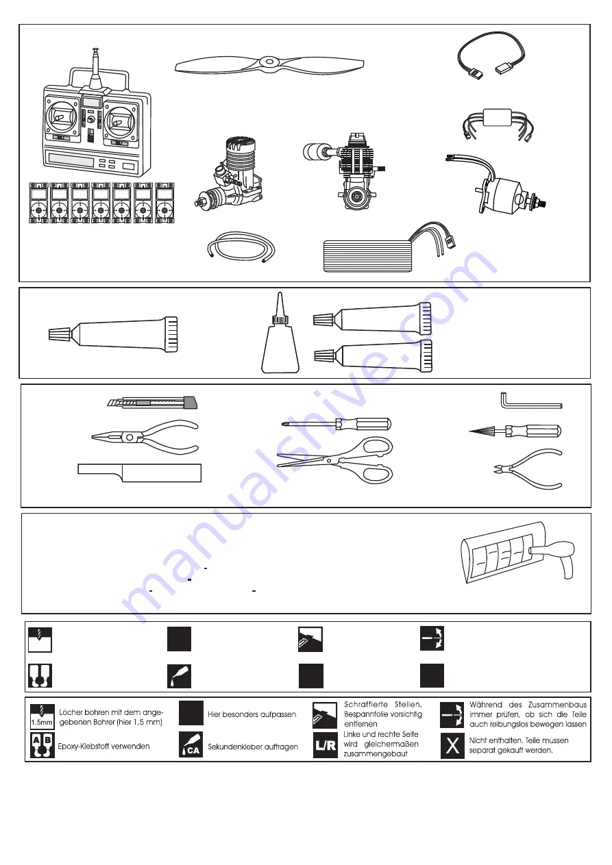
Minimum 6 channel radio
for airplane with 7 servos

.70 ~.91 - 4 cycle

12x6 for .58 - 2 cycle engine
12x7 for .61 - 2 cycle engine
12x7 for .70 - 4 cycle engine
14x6 for .91 - 4 cycle engine

Silicone tube

Extension for aileron
 servo.(x2)

.58 ~ .61 - 2 cycle

.Motor control x1  .Aileron x 2
.Flap x 2  .Elevator x1  .Rudder x1 

SILICON

EPOXY A

EPOXY B

CA

GLUE /

Epoxy Glue (  5 minute type)

Silicon sealer

Cyanoacrylate 
Glue

Epoxy Glue (30 minute type)

Hobby knife

Needle nose Pliers

Phillip screw driver

Awl

Scissors

Wire Cutters

Hex Wrench

.........................................................

.........................................................

.........................................................

.........................................................

.........................................................

.........................................................

.........................................................

.........................................................

.........................................................

.........................................................

.........................................................

Sander

Masking tape - Straight Edged Ruler - Pen or pencil - Rubbing alcohol - Drill and Assorted Drill Bits

REQUIRED ITEMS  /  Zum Betrieb wird benotigt

KLEBSTOFF

1.5mm

A B

!

CA

L/R

Assemble left and right 
sides the same way.

X

Drill holes using the stated

size of drill 
(in this case 1.5 mm Ø)

Use epoxy glue

Take particular care here

Hatched-in areas:

remove covering
 film carefully

Not included.
These parts must be

purchased separately

Check during assembly that these

parts move freely, without binding

Apply cyano glue

!

If exposed to direct sunlight and / or heat, wrinkles can appear. Storing the model in a coll
place will let the wrinkles disappear. Otherwise, remove wrinkles in covering film with a hair-
dryer, starting with low temperature. You can fix the corners by using a hot iron.

Bei Sonneneinstrahlung und / oder Warme kann die Folie erschlaffen bzw. Falten entstehen.
Verwenden Sie ein Warumluftgeblase (Haartrockner) um evtl. Falten aus der Folie zu 
bekommen. Die Kanten konnen Sie mit einem Bugeleisen behandeln. Nicht zuviel Hitze
anwenden

Read through the manual before you begin, so you will have an overall idea of what to do.

CONVERSION TABLE

1.0mm = 3/64”
1.5mm = 1/16”
2.0mm = 5/64”
2.5mm = 3/32”

3.0mm = 1/8”
4.0mm = 5/32”
5.0mm = 13/64”
6.0mm = 15/64”

10mm = 13/32”
12mm = 15/32”
15mm = 19/32”
20mm = 51/64”

25mm = 1”
30mm = 1-3/16”
45mm = 1-51/64”

Li-Po Battery 
LEMONRC 4500 - 18.5v

ESC 80A

Motor Brushless
870Watt (PULSAR 60)

Summary of Contents for Cap 10

Page 1: ...GINE POWERED ALL BALSA PLANE Wingspan approx 1500mm Fuselage lenght approx 1205mm Electric Motor 870 Watt PULSAR 60 Glow Engine 61 2T 91 4T Radio 5 Channel 6 Servos Spannweiter ca 1500mm Lange ca 1205...

Page 2: ...remove covering film carefully Not included These parts must be purchased separately Check during assembly that these parts move freely without binding Apply cyano glue If exposed to direct sunlight a...

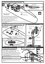
Page 3: ...screws Flap push rod exit L R Aileron servo Aileron push rod CAUTION one of the flap servos is revert servo 2x10mm screw 3 Servo installation Servoeinbau 1 2mm L R Plastic control horn 2x20mm screw L...

Page 4: ...pper Wheel Nylon gear strap 3x12mm screw Fiber glass wheel pant FRONT VIEW BOTTOM VIEW Wooden block Wooden block Nylon gear strap ABS gear cover Fiber glass wheel pant 3mm screw black BOTTOM VIEW 4 3m...

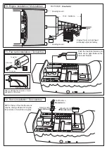
Page 5: ...ngine mounts using fous 3x25mm screws and nuts Trim the fire wall so that your muffler doesn t touch with a knife or Dremel Trim the fire wall so that your muffler doesn t touch with a knife or Dremel...

Page 6: ...bau Cowling mount Cowling mount Engine thrust on balk head is already adjust at factory X To muffler Filler tube To engine Draufsicht NOTE Place of the throttle servos may be change depend of engine F...

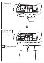
Page 7: ...13 Joining the wing Flachenverbindung Aluminum tube 14 Joining the wing Flachenverbindung TOP VIEW Draufsicht L R Asemble the Left and Right wing the same way TOP VIEW Draufsicht...

Page 8: ...horizontal stabilizer and fuselage where it meets the horizontal stabilizer 6 Insert the horizontal stabilizer into the fuselage and secure it in place using masking tape and allow the epoxy to cure c...

Page 9: ...lace 2mm 2mm WARNING Securely glue together If coming off during flights you lose control of your airplane which leads to accidents 10mm Plastic control horn 2x20mm screw 2 4 Plastic back plate 2 When...

Page 10: ...ugh the rudder Insert the rudder push rod into the rudder control horn Attach the rudder control horn using two 2x25mm screw and a back plate 20 Linkages Anlenkungen 2x25mm screw Rudder servo 2 mm X C...

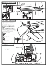
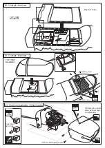
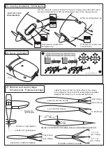
Page 11: ...OP VIEW Draufsicht Magnetic hatch 22 Cockpit Kabinen TOP VIEW Draufsicht 23 Cockpit Kabinen 24 Cowling installation Motorhaube Drill holes for needle valve exhaust pipe and glow plug 3mm 5mm 3x10mm se...

Page 12: ...l range Schwerpunkt Ruderausschlage Sticker 75 78mm Position for right diagram Position for right diagram NEVER FLY BEFORE CHECKING THE CG S REQUIRED POSITION 2 9 3 1 7 1 9 45 50mm 1 7 1 9 51 64 20mm...

Reviews: