background image

102mm

!

Align the mark on both 
mounts with the center 
mark on the fire-wall

Securely attach the engine mount to the 
fire-wall using the four 4x25mm screws.

Position the engine on the engine mount beams so the 
distance from the prop hubto the fire-wall is 102mm/(4”).
Using a pencil, mark th engine mounting plate where
the four holes are to be drilled. Note: Mark the mounting
plate through the engine mounting flanges.

Trim the cowling for
engine and muffler.
Then, position the 
cowling in place.

FRONT VIEW

A

A

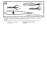
Note the side thrust for motor!

Sturz und Zug beachten!

Reposition the engine on the mounting
beams, aligning it with the holes drilled
in Step 3. Insert one 3x25mm screw through
each of the mounting holes. Apply Silicon
to each of the 3x25mm screws and firmly
secure the engine to the motor mount using
four 3mm nut. 

                             Set the engine on the
                             engine mounting beams.
                             Adjust the spacing of
                             the beams so they are 
                             centered in relation to
           the mounting plate and so they are 
           almost touching both sides of the 
           engine crankcase.

1

3.5mm

A

B

Remove the engine and drill
a 3.5mm hole through the
beam at each of the four marks
made in Step B.

C

D

2.5mm

Drill the hole through the fire-wall
for the plastic pushrod tube

Note: It may be easier to temporarily remove the throttle
arm from the engine to insert the Z bend of throttle push-rod.

Summary of Contents for L4A GRASSHOPPER

Page 1: ...as and seek professional advice if you are unexperienced ACHTUNG Dieses ferngesteuerte Modell ist KEIN Spielzeug Es ist f r fortgeschrittene Modellflugpiloten bestimmt die ausreichende Erfahrung im Um...

Page 2: ...ntrieb Tuning Kraftvoller Kunstflug BOOST 60 Brushless Combo Set Best Nr C3174 LiPO Akku RED POWER 4250 5S Best Nr C4547 Luftschraube 13 8 Best Nr C2846 Silikonkleber Tool Required Empfohlenes Werkzeu...

Page 3: ...sition the engine on the mounting beams aligning it with the holes drilled in Step 3 Insert one 3x25mm screw through each of the mounting holes Apply Silicon to each of the 3x25mm screws and firmly se...

Page 4: ...torspant TOP VIEW Draufsicht SIDE VIEW Seitenansicht Sturz und Zug beachten Sperrholztrager Platten zusammenkleben wie gezeigt ausrichten und Locher bohren Motor nach untenstehendem Schema einbauen Fu...

Page 5: ...4mm HORIZONTAL STABILIZER Cut two slots 3x7mm and 3mm deep along the trailing edge of the horizontal stabilizer 4 Full the elevator out of the horizontal stabilizer Cut away only the film both side 5...

Page 6: ...moving any covering from the airframe please ensure that you secure the cut edge with CA or similar cement This will ensure the covering remain tight B B B B Aluminum wing joiner 6 Apply a thin layer...

Page 7: ...ntil the parts meet exactly with no gaps When you are satisfied with the alignment use a pencil to trace around the left and right of the stabilizer where it meets the fuselage Remove the vertical sta...

Page 8: ...n 1 16 3x12 2 1 1 9 Cut away only the covering Cut away the covering and balsa wood WARNING When removing any covering from the airframe please ensure that you secure the cut edge with CA or similar c...

Page 9: ...TTOM VIEW Unteransicht 4 Connector 3mm connector 3mm connector Aluminum landing gear Hauptfahrwerk 4x30mm screw 4mm nut 3mm connector FUSELAGE Aluminum landing gear Hauptfahrwerk 3mm connector 4mm 4mm...

Page 10: ...Throttle pushrod FRONT TOP VIEW Servo tray Servo tray Elevator pushrod Elevator servo Rudder servo Throttle servo 14 16 15 1...

Page 11: ...Akku Kiettband aus dem PICHLER Sortiment Best Nr C4739 Battery seat bell X Tipp 17 18 Magnetic seating front seating only Magnetic piece CA...

Page 12: ...rod Trial fit the control horn into the slot If the parts will join but with a gaps sand or trim the parts a little at a time until the parts meet exactly with no gaps B B B B Aluminum tube BOTTOM VIE...

Page 13: ...hole on the surface of the top of the wing are pre drilledat factory 2 mm drill bit Aluminum tube inside 3x15mm screw TOP A B 3x15mm screw 2 Secure the wing in place using 3x15mm screw WRONG A B 22 RI...

Page 14: ...ount 220mm Note The rear landing gear mount is pre installed at factory BOTTOM VIEW Unteransicht X Rear landing gear not included IN CASE OF FLOATING USING 3x15mm screw 6 26 25 4 Cut away only the cov...

Page 15: ...27 VQA082 VQA083 0 5mm dia Cable 1 roll 2mm metal tube 4 28...

Page 16: ...hwerpunkt IMPORTANT Please do not clean your model with pure alcohol only use liquid soap with water or use glass cleaner to clean on surface of your model to keep the colour not fade All details are...

Reviews: