background image

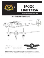
Radio control model 

Wingspan approx.                                   83 in.           
Fuselage length approx.                      57.5 in.           
Glow Engine            7.45cc 2T /11.5cc 4T (x2)            
Electric Motor    870 Watt Brushless motor x2           
Radio                            6 Channel / 10 Servos             

INSTRUCTION MANUAL  

WARNING!

 This radio controlled model is NOT a toy. If modified or flown carelessly it could go out of control and

cause serious human injury or property damage. Before flying your airplane, ensure the air field is spacious enough.
Always fly it outdoors in safe areas and seek professional advice if you are unexperienced

.

LEGEND MODELS

L

Summary of Contents for P-38 LIGHTNING

Page 1: ...nel 10 Servos INSTRUCTION MANUAL WARNING This radio controlled model is NOT a toy If modified or flown carelessly it could go out of control and cause serious human injury or property damage Before flying your airplane ensure the air field is spacious enough Always fly it outdoors in safe areas and seek professional advice if you are unexperienced LEGEND MODELS L ...

Page 2: ...del in a coll place will let the wrinkles disappear Otherwise remove wrinkles in covering film with a hairdryer starting with low temperature You can fix the corners by using a hot iron Read through the manual before you begin so you will have an overall idea of what to do CONVERSION TABLE 1 0mm 3 64 1 5mm 1 16 2 0mm 5 64 2 5mm 3 32 3 0mm 1 8 4 0mm 5 32 5 0mm 13 64 6 0mm 15 64 10mm 13 32 12mm 15 3...

Page 3: ...e flap push rod installed as shown Using the pencil trace around the servo where it meets the servo mount Connector included Remove the servo out of the wing Place the servo onto the adhesive tap as shown With the pencil trace around the servo where it meets the adhesive tape Adhesive tape included Adhesive tape Servo mount Pencil line Adhesive tape Peel the bottom cover Peel the top cover With th...

Page 4: ... 2 Wing CENTER WING Top view Adhesive tape keep the extension in place Cut away the covering for the extension cord exit CENTER WING Bottom view The center wing with the flaps in closed position The center wing with the flaps in opened position ...

Page 5: ...sion with the aileron servo cord before attach the hatch to the wing Note the aileron extension must 700mm long or use two 300mm long 2 4 2x30mm screw Servo mount Flap push rod Note the connector is turn down Note the connector is turn down Connector RIGHT WING Bottom view Connector 2 3 Wing 3A From Step 3B to Step 3I follow the procedure as described in the 1 WING section 3J 3K ...

Page 6: ... other side of the center wing Slide the aluminum tube into the left and right side of the center wing 19x317mm aluminum tube 12x182mm aluminum tube 2 2 6x12mm wooden dowel 6x12mm wooden dowel 2 CA Glue the dowel only Bottom view CENTER WING Bottom view CENTER WING 4 Wing ...

Page 7: ...eet the center wing Aileron extension 4x20mm screw Secure the outer wing in place using 4x20mm screw 4x20mm screw 2 2 Check the ailerons and flaps functions move in the correct before attach all hatches to the bottom of the wing 5 Wing ...

Page 8: ...ith the center mark on the balk head L R 3x25 8 Washer 8 Nut 3mm 8 Secure the engine to the engine mount using four 3x25mm screws Insert the Z bend into the hole on the throttle lever of engine Note It may be easier to temporarily remove the control arm from the carburetor to insert the Z bend C C 132 134mm 4x30mm screw 8 8 B B 132 134mm SIDE VIEW TOP BOTTOM 6 Engine mounts 7 Engine 6A 6B ...

Page 9: ...3mm hole through the plywood at each of the four marks marked Note The aluminum motor mounting included with electric motor set 5x70mm 8 5mm nut 24 washer 32 5mm 3mm Align the mark on the motor mounting plate with the center mark on the balk head X Firewall 132 134mm B B B B SIDE VIEW L R L R 8 Electric Motor 9 Fuel tank FDP FDP CA CA Installing the Lipo Battery Stand Lipo Battery stand FUSELAGE T...

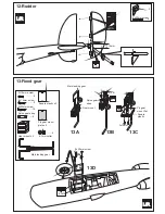
Page 10: ...vator servo RIGHT FUSELAGE Top view Elevator Pushrod Connecting rod 6 L R Throttle pushrod Rudder pushrod 2 mm RIGHT FUSELAGE Top view 10 Hatch Rudder Pushrod 11 Servos L R FUSELAGE Bottom view Bottom hatch Bottom hatch 30x4mm nylon bolt 4 Secure the Bottom hatch in place using the 30x4mm nylon bolt Cut away only the covering CA 11A 11B 11C ...

Page 11: ...unt 3x12m Nylon gear strap 2mm 3x15mm Ply gear mount flat Square plastic 2mm 4 7mm collar 4 Ply gear mount plate x 2 Gear mount x 2 3x20mm screw 8 3x12mm screw 16 Nylon gear strap 4 Square plastic x 2 Main landing gear 3x15mm screw 8 L R 12 Rudder 13 Fixed gear 13A 13B 13C 13D ...

Page 12: ...ose gear Nose gear base plastic Nose gear arm Nose gear push rod Nose gear control arm 3mm 3x20mm 4 Washer 4 Nut 3mm 4 MAIN FUSELAGE Bottom view Cut the opening Nose gear mount Nose gear arm X 14 Nose gear 15 Main gear Electric retract 16 Nose gear Electric retract ...

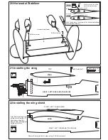
Page 13: ...ntal stabilizer LEFT FUSELAGE RIGHT FUSELAGE 19 Horizontal Stabilizer RIGHT FUSE LEFT FUSE 6x60mm wooden dowel 4 12x108mm aluminum tube 2 L R Secure the aluminum tube and wooden dowel in place using Thin CA glue Aluminum tube Wooden dowel 6x60mm CA 12x108mm Wooden dowel 6x60mm 18 Horizontal Stabilizer A 8mm A A B 60mm B A 8mm A A B 60mm B ...

Page 14: ...e of the fuselage top shield until this is achieved RIGHT LEFT FUSELAGE TAIL BOOM WING 2 mm 3x15mm screw 2 mm drill bit Aluminum tube 20A Drill through both the balsa block and aluminum tube Balsa block TOP Note The holes on the bottom of the Horizontal stabilizer are pre drilled at factory 20 Horizontal Stabilizer 21 Installing the wing 22 Installing the wing shield Secure the wing shield in plac...

Page 15: ...elage 24 Installing the cockpit Secure the cockpit in place using 2x8mm screws 25 Cowling Secure the cowl in place using 2 5x12mm screws 2 5x12mm screw 8 L R Note The L Cowl for LEFT fuselage and R Cowl for RIGHT fuselage looking from REAR to FRONT and TOP view COWL BOTTOM VIEW COWL BOTTOM VIEW Gear door CA Hinge 26 Gear door 26A 26B ...

Page 16: ...ON RETRACT LANDING GEAR IN RETRACTED POSITION RETRACT LANDING GEAR IN EXTENDED POSITION Spring not include Cotton thread not include Gear door Cotton thread not include Note you can find the same spring in old ball point pen Fuselage Fuselage Gear door GEAR DOOR IN OPENED POSITION CA Frame Hinge Frame CA CA Gear door 27 Gear door 27A 27B ...

Page 17: ...Gear door main fuselage Cotton thread not include Spring not include Gear door Bottom view Balsa block not include CA CA CA CA 28 Gear door 28A 28B 28C 28D ...

Page 18: ...rner of the backing and cut off with scissors Arrange sticker on model and when satisfied adhere the corner without backing Carefully peel back the rest of the backing while at the same time adhering the rest of the sticker Try not to make air bubbles if there are some carefully puncture sticker center of bubble but not model surface with the tip of the knife or sharp pin and squeeze out the air A...

Page 19: ...side L R Kill mark only for one side 32 Decal Skidoo version IMPORTANT Please do not clean your model with pure alcohol gasoline or strong sloven only use kerosene or liquid soap with water or use glass cleaner to clean on surface of your model to keep the colour not fade ...

Page 20: ...m behind the leading edge 115 120mm WING ROOT 8 10mm 8 10mm 30 35mm 10 12mm 10 12mm 25 30mm AILERON FLAP ELEVATOR RUDDER 25 30mm Position for right diagram Position for right diagram WARNING Never fly before checking the Cg s required position 34 Balance 35 Control ranges ...

Reviews: