background image


VS Security Products LTD


ZZ201216, ZZ201217


 Page 10 of 31


6.1.1 Erasure of Hard Drives and Large Backup tapes LTO, DLT, 3480 series.


1.


Connect the unit to the power supply


2.


Activate the power switch on the rear of the unit.


3.


Once the unit is ready, gently slide the hard drive into the aperture on the left had side of the degausser


NOTE:  Hard  drives  are  manufactured with  the  disc  mounted  at  one  end  of  the  assembly,  the  hard  drive  must  be 

placed  in  the  cavity  effectively  on  its  edge.  If  this  is  not  observed  the  lid  will


not  latch  down.  Under  no 

circumstances should excessive force be used to close the lid.


4.


When the erase cycle is complete, the hard drive will emerge from the degausser on the right

-

hand side


6.1.2 Erasure of 

2.5” & 1.8” 

Hard Drives and small media 4mm and 8mm cassettes etc.


To erase small hard drives 

2.5” & 1.8” 

and also small media 4mm and 8mm cassettes etc., they should be placed in the 

Small Media Carrier supplied with your degausser


1.


Connect the unit to the power supply


2.


Once the unit is ready, gently slide the small media carrier into the aperture on the left

-

hand side of the degausser


3.


When the erase cycle is complete, the small media carrier with the hard drive will emerge from the right

-

hand side of 

the degausser


6.1.3 ERROR


MESSAGES


If  the  DATAGONE  LG  PLUS  is  not  performing  correctly  the  following  error  messages  may  be  displayed.  To  validate  the 

message switch the unit off and the on again using the power switch on the rear of the unit.


START UP ERROR


EXIT SENSOR TRUE


If this message is displayed the Input optical sensor may be contaminated with dust or dirt. To resolve this problem the Input 

sensor will need to be cleaned. Please refer to maintenance section 12.1.


EJECT ERROR


SENSOR 1 JAMMED


If this message is displayed the output optical sensor may be contaminated with dust or dirt. To resolve this problem the 

sensors will need to be cleared. Please refer to maintenance section 12.2.


6.2 Operation with Erasure Logging


      Operation


When erasure logging is required, simply connect the degausser to a PC or laptop and open the logging program. This will 

log all the information related to the erasure and provide a printed report if required. The information logged includes details 

of the degaussing company (including the operator and supervisor), media owner, degausser machine type, serial number, 

part number and size of the Hard Drive or Tape. 


Information is entered onto the software via keyboard or optional barcode scanner to speed up the data entry, if required. 

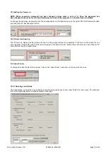
When the logging program has been opened on the PC and the degausser is connected, the operator simply clicks on the 

Find  Machine

” 

button  for  all  the  unit  details  to  be  automatically  entered  into  the  log  including  model,  serial  number  and 

firmware version. The degausser display will show it is in remote mode controlled by the PC.


Further data regarding operator, customer and media is then entered via keyboard (or optional barcode scanner) before the 

Hard Drive or Tape is placed into the degausser and the lid closed. The erasure is commenced by clicking the 

Destroy

” 

button on the screen which activates the charging of the powerful degaussing magnetic field.


A window opens on the screen showing the progress of the degaussing cycle. When the display shows the degauss cycle is 

complete the lid can be opened and the media removed. 

The entire process takes just 9 seconds. 

Throughout the whole 

erase  cycle  the  on

-

board  processor  monitors  the  erase  procedure ensuring  that  it  is completed  correctly.  The  operator  is 

immediately alerted to any interruptions in the cycle by messages on the screen.


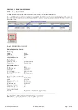
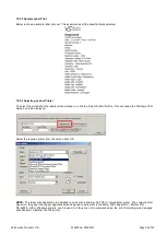
The  lower  portion  of  the  screen  now  shows  all  the  details  of  the  erasure  including  Date,  Time,  Media  Serial  Number, 

Capacitor  Voltage,  Magnetic  Gauss  Field  and  confirmation  that  the  media  was  degaussed  successfully.  If  this  data  is 

highlighted  and  the  print  button  pressed  all  the  details  on  the  screen  along  with  all  the  data  entered  will  be  printed  as  a 

report. As new media is erased the details will be added to the Media Processed Log in the lower half of the screen.


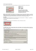
By  highlighting  erase  records,  the  logs  of  one  or  more  can  be  printed  as  required.  There  is  a  Supervisor  Section  in  the 

Software which is Password protected. This allows the Supervisor to decide which fields are required and which fields must 

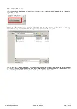
be completed by the Operator. The log record is stored on the PC and can be archived at any time or exported as a .csv file.


To use the degausser without the Data Logging Software disconnect the USB Cable and reboot the degausser.


Summary of Contents for Datagone LG-PLUS ZZ201216

Page 1: ...ZZ201216 ZZ201217 Rev 14 ...

Page 2: ... are placed out of range CAUTION it is recommended that magnetic storage media is kept at least 1 metre 3 Feet from the degausser IMPORTANT the power on off switch used on this equipment is not an isolating switch it is recommended that this equipment should be operated from a separate switched isolator COPYRIGHT This document is the property of VS Security Products Ltd and it may not be reproduce...

Page 3: ...n infringement SOME JURISDICTIONS DO NOT ALLOW THE EXCLUSION OF IMPLIED WARRANTIES SO THE ABOVE EXCLUSION MAY NOT APPLY TO YOU YOU MAY ALSO HAVE OTHER LEGAL RIGHTS WHICH VARY FROM JURISDICTION TO JURISDICTION 6 Limitation of Liability VS SECURITY PRODUCTS LTD SHALL NOT BE LIABLE FOR ANY INDIRECT SPECIAL INCIDENTAL OR CONSEQUENTIAL DAMAGES OR LOSS INCLUDING DAMAGES FOR LOSS OF BUSINESS LOSS OF PROF...

Page 4: ...n 6 4 Introduction to the Datagone LG PLUS Degausser 6 5 Software Installation 6 6 Operation Guide 9 7 Erasure Logger Software 11 8 Interrogating the Database 16 9 Printing Records 17 10 Supervisor Screen 19 11 Safety Recommendations 29 12 Maintenance 29 This document refers to Datagone LG PLUS part no s ZZ201216 115v 60Hz ZZ201217 230v 50Hz ...

Page 5: ...l 230v 50Hz ZZ201217 TEMPERATURE 5 C 41 F to 40 C 104 F HUMIDITY 10 to 80 non condensing MOUNTING Free standing table top DIMENSIONS 14 3 x 19 2 x 14 3 36cm x 48cm x 36cm DIMENSIONS PACKED 19 5 x 29 1 x 19 5 50cm x 74cm x 50cm WEIGHT 73 lbs 33kg PACKED WEIGHT 84 lbs 38kg COMPATIBLE Windows 8 Windows 7 Windows Vista Windows XP OPERATING SYSTEMS SP3 or higher 32 bit only CONNECTIVITY Bi Universal se...

Page 6: ...rom the packing box 3 2 Power Wiring Power connection is made to the degausser in the form of an IEC type electrical lead supplied The user should ensure that their power supply meets those outlined on page five SECTION 4 INTRODUCTION TO THE DATAGONE LG PLUS DEGAUSSER The Datagone LG PLUS is a high energy hard drive Degausser They erase Longitudinal Magnetic Recorded LMR and Perpendicular Magnetic...

Page 7: ...Z201217 Page 7 of 31 Close all Windows programs that are running and click NEXT Tick the box to confirm you have read and accept the software licence conditions and click NEXT Check the suggested destination is acceptable and click NEXT ...

Page 8: ...VS Security Products LTD ZZ201216 ZZ201217 Page 8 of 31 Select the number of Users and click NEXT Click NEXT to start the installation Click FINISH to complete the installation of the Logger Software ...

Page 9: ...should not be reused as they are stressed in the erasure process and parts can be damaged Backup tapes cannot be used after erasure as the control track may be erased in the degaussing process Control Panel The DATAGONE LG PLUS degausser has been carefully engineered for convenience and simplicity of operation As such an LCD and push button are all that is required The features provided are outlin...

Page 10: ...rt if required The information logged includes details of the degaussing company including the operator and supervisor media owner degausser machine type serial number part number and size of the Hard Drive or Tape Information is entered onto the software via keyboard or optional barcode scanner to speed up the data entry if required When the logging program has been opened on the PC and the degau...

Page 11: ...is completed It is possible to interrogate the database to retrieve the destruction information record This record or a number of records can be printed out using any printer attached to the machine including network printers If a suitable label printer is attached to the system it will print a label every time the machine destroys media The label contains data about the media that was destroyed 7...

Page 12: ...ning Windows XP then it will be necessary to install the USB drivers manually If you received a CDROM installation disc from VSSP the FDTI USB drivers and installation instructions are on the CDROM for each operating system If you did not receive a CDROM installation disc from VSSP then it will be necessary to download the FTDI USB Drivers and installation procedure from the FTDI web site http www...

Page 13: ...be used to clear all the entries in the panel if required 7 3 1 Bar Code Scanner If the bar code scanner has been installed it can be used to enter bar code data such as serial numbers directly into the relevant data entry box So if you wanted to read a bar code serial number into the Serial No data entry box first ensure that the cursor is in the box either click in the box with the mouse or use ...

Page 14: ...s have entries destruction will commence and the following screen is displayed When the destruction process has completed the destruction data is shown in the Media Processed box The data shown in the Media Processed box is a snapshot of the data record and shows the key data Record Number Date of Destruction Time of Destruction Media Serial Number Capacitor Voltage Magnetic Field Gauss Result Deg...

Page 15: ... the Windows Print Spooler the Windows Print Spooler is responsible for sending the print Data to the selected printer If the selected printer is switched off or disconnected there is no notification of this fact back to the Logger Application The print job will sit in the Windows Print Spooler Queue until the selected printer becomes available At this point the print job is printed as are any oth...

Page 16: ...repeated for each record that is to be viewed 8 2 Resuming Destruction after Interrogation When the database records are being interrogated the DESTROY button is disabled To enable the button click the Resume button This will then cause the machine to check that the VSSP machine is still connected When the VSSP machine is located the DESTROY button will be enabled NOTE Any Processing Company and M...

Page 17: ...0 06 2014 14 31 28 Media Destruction Record Company Name VSSP Operator Victoria Supervisor Brian Degaussing on Site Yes Media Owner Company Name ICL Engineering Department Engineering Media Information Type HDD Serial Number 79429 499 Capacity Unknown Part Number IBM 4430 946 Security Classification None Remarks Search Failures Degausser Crusher Details Date 20 06 2014 Time 12 31 09 Degausser Crus...

Page 18: ...ey down and click the individual records to be printed When you have selected the records to be printed click the Print button the normal print dialog box will be displayed Select the printer to which the record is to be sent set the number of copies required and click OK The Record Data is now sent to the printer NOTE Each record is printed on a separate page 9 3 Resuming Destruction after Printi...

Page 19: ...nter the Supervisor screen the correct password must be entered The default password is password Note that this is all lower case The password can be changed in the supervisor screen NOTE If supervisor password has been changed please make a note of it Once changed it cannot be reset to the default password even if the program is un installed and re installed If the correct password is entered the...

Page 20: ...een This allows the supervisor to specify exactly which Data Entry Boxes are to be displayed on the Logger main screen On the Mandatory sub panel a tick box with a tick in it will cause the corresponding Data Entry Box to be Mandatory e g it must contain some data prior to the Destruction button being clicked If the Tick Box is not ticked then the corresponding Data Entry Box is not Mandatory and ...

Page 21: ...0 4 Printer Line Spacing The Printer Line Spacing setting allows the lines on the printed records to be adjusted If the lines on the printer are too close together increase the value of the line spacing set in the data entry box Most printers will require a value of about 70 some printers require a higher value 10 5 Label Printer To display the Label Printer Set Up screen click on the Label Printe...

Page 22: ...n This will cause the Windows Print Setup box to be displayed Select the required printer from the list and click OK NOTE The label print application is designed to work with a Brother QL 700 or compatible printer The correct printer paper i e the paper the Logger Application was designed to work with is the 62mm Wide Paper Roll Brother P N DK 22205 Other Windows printers can be used but they are ...

Page 23: ... sit in the Windows Print Spooler Queue until the selected printer becomes available At this point the print job is printed as are any other queued print jobs Logo Offset The logo offset sets the position that the logo is printed on the label Its default position is Top Margin 1 Logo Offset 1 This causes the logo to be printed on the Top Left of the label 10 6 Database To display the Database scre...

Page 24: ...ile dialog box The supervisor can then choose a location e g drive and or folder to store the archive file The supervisor can also name the file as required The file name can be defined by the supervisor however it is recommended that the file extension is csv as the file format is a comma separated values file and choosing a csv file extension allows suitable programs such as a spreadsheet to aut...

Page 25: ...18 Media Info PN 19 Media Info Class 20 Media Info Remarks 21 Capacitor Voltage Volts 22 Magnetic Field Strength Gauss 23 Result Degaussed Crushed Failed etc Field number 01 is the first field If the file is given a csv file name extension suitable programs such as a spreadsheet can automatically open and display the file 10 6 3 Database Location The example below shows the default database locati...

Page 26: ... printer name and the database file name NOTE Do not change the contents of the ini file the logger application may become unusable 10 6 4 Moving the Database The storage location and name of the database file can be moved by clicking the Move Database button NOTE This will archive the current database and create a new database First the existing database must be archived Clicking the OK button wi...

Page 27: ...the windows save as dialog navigate to the directory you wish to save the database file in Enter the required name for the database and click save The below dialog box shows the name and location of the new empty database file Click OK The database screen now shows the name and location of the new database and the main screen shows no records ...

Page 28: ...er on the network it uses the SMB File sharing protocols to allow Windows Sharing The below database screen shows that the database has been created in the network location QNAP 1 Test and the filename is new_database csv It is important that the network location chosen must ALWAYS be available If the Logger application is started and the network location is not accessible the Logger application w...

Page 29: ...removed by anyone other than trained VS Security Products technicians 12 1 Cleaning the Input Optical Sensor The Input Sensor is an optical device that looks across the degauss chute to detect the media when it enters the unit If the media is dusty or the unit is used in a dusty environment the sensor can become contaminated and not see the media This will result in the unit exhibiting a fault and...

Page 30: ...very dirty the drives may become stuck and not release after the degausser has fired Under these circumstances the chute should be cleaned NOTE Before cleaning takes place the unit must be unplugged from the mains supply The chute should be cleaned using a soft cloth or paper hand towel If the dirt is sticky then a small amount of a cleaning agent such as Isopropyl alcohol IPA can be used on the c...

Page 31: ...VS SECURITY PRODUCTS LIMITED VS AND ASSOCIATES Unit 17 Pegasus Court 3160 Texas Hill Road North Lane Placerville Aldershot California GU12 4QP 95667 UK USA ...

Reviews: