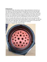
Pin 1: Main Power Wire 12V + ;Red, 10 gauge wire
Pin 2: Main Ground Wire ; Black, 10 gauge wire
Pin 3: Hose Reel Power 12v + ; Red, 10 gauge wire
Pin 4: Accessory Power Feed 12v + ; Red, 10 gauge wire
Pin 5: Light Bar Signal Wire; Red wire: L/S (rb)
Pin 6: Strobe Signal Wire; Yellow wire: SV (rb)
Pin 7: Left (driver side) Boom Signal; Yellow wire: LBV (rb)
Pin 8: Middle Boom Signal; Green wire: MBV (rb)
Pin 9: Right (pass. side) Boom Signal; Orange wire: RBV (rb)
Pin 10: Proportional Valve Signal 1; Pink wire: PM1 (mb)
Pin 11: Proportional Valve Signal 2; Blue wire: PM2 (mb)
Pin 12: Flow Meter Signal; White wire: FLO (mb)
Pin 13: Total Control Remote Engine Starter; Green Wire: RF1 (lb)
Pin 14: Total Control Remote Engine Kill Switch; White wire: RF2 (lb)
Pin 15: Total Control Remote Choke Down; Pink wire: RF3 (lb)
Pin 16: Total Control Remote Choke Up; Blue wire:RF4 (lb)
Pin 17: Total Control Remote Throttle Down; Orange wire: RF5 (lb)
Pin 18: Kill Switch Signal; Orange wire: KILL (mb)
Pin 19: Starter Signal; Yellow Wire: STRT (mb)
Pin 20: Engine Voltage Sensor: Gray wire; VEN (mb)
Pin 21: Total Control Throttle Up: Yellow Wire; RF6 (lb)
Pin 22: Total Control Remote Hose Reel Button: Purple wire; RF17 (lb)
Pin 23: Actuator 5v+: Red wire; +5v (mb)
Pin 24: Not used
Pin 25: Total Control Remote Lights: Gray wire; RF8 (lb)
Pin 26: Not used
Pin 27: Choke Signal: Green wire; CHK (mb)
Pin 28: Not used
Pin 29: Throttle Signal: Blue wire; THR


