background image

15

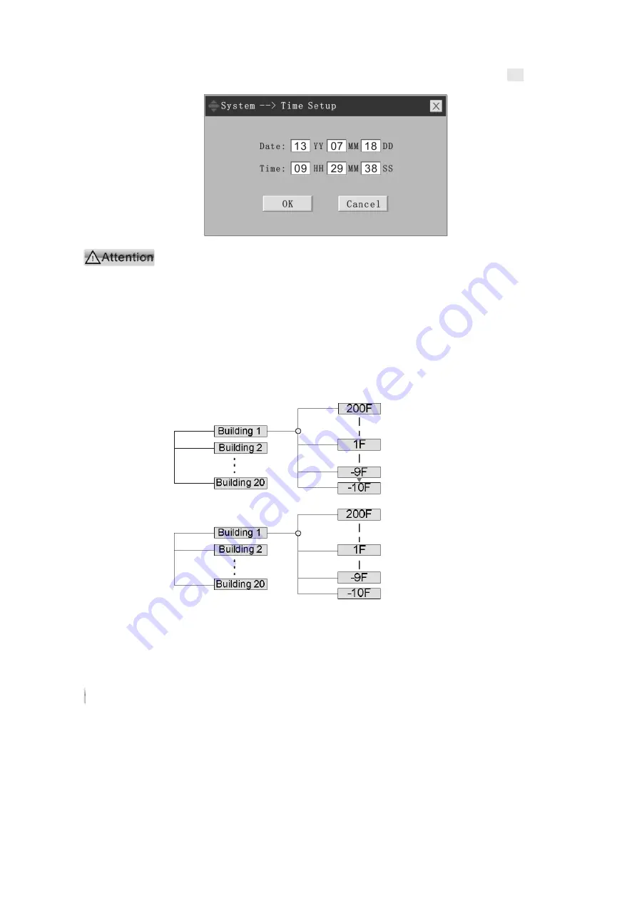
4.1.1 Time setup

The time setup interface is as follows: enter into proper date and time, click the OK button,

and the system will save the time set by the user.

Figure 4

3 Time setup interface

In the networking system of multiple hosts, as the host time is required

to be the same, all hosts in the system will take time of the concentrator as criterion.
This means other hosts will align with the time setup of the concentrator
automatically and synchronously, the system time will be synchronized to time of
the concentrator even if other hosts have set the time. Therefore, only the
concentrator has the effective time setup function in the networking system.

4.1.2 Building setup, floor setup

The setup of building and floor is to familiarize the system with the application-engineering

environment. The whole area governed by the system is logically partitioned as follows by the 3
geographic orientation setup:

The system can govern 20 buildings at most, with each building having 10-200 floors. For

a certain engineering, effective buildings and floors are required to be registered by clicking on
the registration column in the corresponding form; "

" means registered, "×" means

unregistered.

The building and floor setup shall be carried out at the beginning of

engineering commissioning, as other setups all base on these data. The problem of
skip floor can be solved by floor registration, that is, some of the buildings may not
have a certain floor, like 4F, thus the registration of that floor can be cancelled and
the system will consider 3F and 5F are adjacent and all linkages can be scrolled
normally.

Building setup:

the building can be named in "location description"; the initialization

value in the figure is "building 1-N".

Attention

Summary of Contents for MN3010E

Page 1: ...MN3010E Fire Alarm Control Panel USER S MANUAL ...

Page 2: ...s operations It has the capabilities of comprehensive field programming and solving complex linkage relation setup It imitates Windows operation interface which is easy to learn and use and to enter Chinese characters The maximum capacity of a single equipment reaches 324 bus alarm linkage control points and 20 units can be networked which can also be networking with other fire alarm control by th...

Page 3: ...he panel 5 3 2 2 Start up and power on 9 3 2 3 Login operation of the users 9 3 2 4 Special function keys of the system 11 3 2 5 Input of characters 12 Chapter 4 System Configuration Details 14 4 1 System setup 14 4 1 1 Time setup 15 4 1 2 Building setup floor setup 15 4 1 3 Networking setup 16 4 1 4 Password setup 18 4 1 5 Indicating panel setup 19 4 1 6 Power setup 20 4 1 7 Printer setup 20 4 1 ...

Page 4: ...l operations 40 4 5 5 Historical deletions 40 4 6 Special operations 41 4 6 1 USB equipment data backup 41 4 6 2 USB data load 42 4 6 3 Bus quality check 43 4 6 4 Document reset 43 4 6 5 Statistics 44 4 6 6 LED brightness control 44 4 6 7 LCD timed power off 44 4 7 About 45 Chapter 5 Alarm Function 46 Chapter 6 Analysis and Elimination of Possible Causes of the Fault 51 Chapter 7 Appendix 53 Appen...

Page 5: ...le and historical file of the system thus facilitating the system maintenance It adopts the non polarity two bus intelligent alarm linkage pattern and can connect 324 intelligent detectors or intelligent modules at most The addresses of module detectors can be mix programmed optional 1 324 It supports interconnection of 20 VST 3010W control units and the maximum system capacity after networking re...

Page 6: ... for alarm message and routine maintenance and query interface Input device The system transplants the computer standard peripheral interface panel buttons or USB interfaced keyboard button as input devices which brings much convenience for the user to set up and maintain the system Power supply The power supply is used for all internal equipment in the overall system The system adopts the special...

Page 7: ...nd fault messages for future reference Fire indicating panel The fire indicating panel is called floor indicating panel and its application is expanded in the system which can be used as both building indicating panel and floor indicating panel The model of indicating panel accessed to the system is JB FSD 982 1 5 Technical parameters of system products 1 5 1 Power supply Main power supply AC 220V...

Page 8: ...cation by above checks power on and carry out simple tests of the control unit and verify whether power supply and basic functions such as button and indication functions of the control unit operate normally without connecting the peripheral equipment 2 2 4 Check and connection of external equipment Check the conditions of the bus connected with the control unit and measure the insulation resistan...

Page 9: ... alarm enquiries and control The indication in the above figure is detailed as follows Indication function zone Figure 3 2 Indication function zone No Silk screen characters Light color Function description 01 POWER ON Green The indicator light will be on when the mainboard is normally supplied by the host or backup power supply The illuminating of the indicator light does not indicate other syste...

Page 10: ...em detects the alarm of host power supply regardless of fault type The power fault may cause the overall system not to function correctly and thus the indicator light is equipped specially 09 SOUNDER FAULT Yellow The indicator light will be lit when the acousto optic alarm apparatus or far sound equipment alarm bell in the system goes wrong 10 SELF TEST Yellow The indicator light will be lit when ...

Page 11: ...atus before power off when the system is switched on again after power off 4 MUTE function key Press MUTE key to mute the sounds of interior buzzer fire indicating panel and graphic display device in the fire control room Under mute state the buzzer and other audible alarm apparatus will be restarted in case of any new alarm MUTE key is the only key without password protection in the system It wil...

Page 12: ...store command immediately and the files currently set by the regional units will lose this update which means the data set since last storage will not be saved automatically Therefore if multiple debuggers operate at the same time please disconnect the connecting line of the host being set temporarily before inputting large data volume 9 F1 function key Pressing F1 on the panel will switch to the ...

Page 13: ...igure 3 5 Status and meaning of icons 3 2 2 Start up and power on The power supply required for normal operation of the system is AC 220V 20 50Hz The equipment must be well grounded After confirmation of these operating environments power on and start up The display will show the following prompt after power on Figure 3 6 Initialization interface At this moment the system will check and load the d...

Page 14: ...atchman is not allowed to enter the system setting interface and can login in check and operate through the panel keyboard only The system will record the operation content of each user to facilitate the responsibility tracing therefore the password shall be kept strictly confidential and carefully managed and be kept away from irrelevant personnel 3 2 3 1 Login of super user system debugger and s...

Page 15: ...ns in via panel keyboard The watchman can login in directly via panel of the control unit and it is only required to operate the panel Login operation Under not logged in state press LOGIN on the panel pop up the password input window and enter into the password according to the numeric keys on the panel keyboard Press ENTER to confirm after inputting the password and LOGIN indicator light is lit ...

Page 16: ...erface or log out interface Ctrl Space Switch to Chinese input method or exit Chinese input method Shift Space Switch over Quanpin input method zone bit code input method Move left the cursor position Move upward the cursor position Move right the cursor position Move downward the cursor position Del Delete text characters at the right side of the cursor None Back Space Delete text characters at t...

Page 17: ...witch over Quanpin input method zone bit code input method Zone bit code input method is cancelled when the panel keyboard is used for operation only Press to switch over digital input T9 input method alphabet input 3 2 5 1 Quanpin input method Only support word input not support word group input Enter rightful phonetic alphabets and press SPACE key to prompt the lookup floating window as shown in...

Page 18: ...menus related to the system configuration including system setup bus setup and linkage setup The following figure is the list of menu setup Figure 4 1 List of menu setup 4 1 System setup Click on SYSTEM SETUP menu and pop up the submenu as shown in Figure below Figure 4 2 System setup menu ...

Page 19: ... application engineering environment The whole area governed by the system is logically partitioned as follows by the 3 geographic orientation setup The system can govern 20 buildings at most with each building having 10 200 floors For a certain engineering effective buildings and floors are required to be registered by clicking on the registration column in the corresponding form means registered...

Page 20: ... can be entered via location description of detector or module For example if an equipment floor is between 2F and 3F of the building and is affiliated to 2F the location of detectors at the equipment floor can be set as 2F with the location description of equipment floor between 2F and 3F The building and floor setup must be carried out prior to other setups otherwise corresponding alternatives a...

Page 21: ...ter the same transmission rates have been set for all hosts Selection of networking transmission rate 10K 20K 50K and 100K can be selected as the networking transmission rate The rate is not the faster the better and shall be selected based on the following situations Number of networked hosts Length of networked bus distance between hosts Type of networking transmission line Number of networked h...

Page 22: ...connect 2 5 hosts with a transmission distance less than 1000m and a transmission rate of 20K The number of transmit receive packages on the bus may be observed by the menu of special operation bus quality inspection If both numbers differ greatly it means the success rate of communications is relatively low and the transmission rate shall be reduced or the transmission environment shall be improv...

Page 23: ...e used as the basis of responsibility tracing in case of accidents Therefore users of each level must keep the passwords in confidence and from leaking Initial password for the system administrator is 111111 The 10 groups of initial passwords for watchmen are 0000 1111 9999 After system delivery please change these passwords into those easy to memorize by yourself and hard to guess by others The s...

Page 24: ...hinese characters or 20 English characters Building and floor if the type of indicating panel is building indicating panel the floor information can be deemed as location display information only when there is not fault alarm of location description If the fire indicating panels are large in number or long in connection it is suggested to use the twisted pair with large diameter and to use the shi...

Page 25: ...nting paper The shiny side of printing paper shall be upward for the thermal printer SPRT 02 system is set as thermal printer The jumper hat on the printer shall be removed or jump to one side Its baud rate is set as 9600BPS 4 1 8 System rename The system name in the title bar can be changed by selecting the function The interface is as follows Figure 4 13 System rename interface Apart from renami...

Page 26: ...e line by line sheet setup of detector module As setup of the system imitates the spreadsheet of Windows operation interface most of the operations are completed by the mouse which operates drop down box horizontal scroll bar and vertical scroll bar The spreadsheet allows the setup of detector module to be simple unified intuitive and easy to understand Operating methods of the spreadsheet are exa...

Page 27: ...nterface photo electricity temperature sensing cable and pressure switch refer to Appendix 1 for the list of all equipment types available in the system currently If the equipment to be accessed by the user is relatively special and is not covered by the list it can be added by the function of equipment type add Refer to related instructions of equipment type add function for the specific operatio...

Page 28: ... location descriptive information of detector module is as shown in the following figure As can be seen from the figure the system initializes location description of each detector module to blank and the user shall add or revise it as required If the position description has not been set building name floor number room number will be displayed at alarm the user may revise the position description...

Page 29: ...mber floor number and room number are not checked boxes before them are not ticked it means the original setting is not changed if building number is checked box before it is ticked it means the building number is the same as that of address 1 if floor number and room number are checked boxes before them are ticked and are set according to floor number and room number of address 1 and options sele...

Page 30: ...tarting point and the property value of each equipment is set according to different setting mode sequence setting properties in the first part until reaching the end address Example 1 double click column header of equipment type and set interface photo electricity for the first part with start address 1 end address 324 and same setting mode then the setting result is as follows the equipment type...

Page 31: ...l equipment in a certain loop is required to be modified enter 0 at address The address value shall lie between 1 and 324 as each loop in the system can accommodate 324 equipment at most If out of range the system will give the following prompt Figure 4 30 Prompt of address over range Click on OK and re enter into correct address information 4 2 3 Add equipment type The function of adding equipmen...

Page 32: ...ion column click on OK button to save new setting and exit otherwise click on CANCEL button to retain original setting and exit 4 3 Linkage setup The submenu of linkage setup is as follows Figure 4 32 Linkage setup menu 4 3 1 System linkage setup The linkage setup of this system adopts several unified man computer interaction interface and is suitable for the linkage relation setup in different zo...

Page 33: ...play another linkage condition when any of the above operations is carried out Cond 1 3 at top left corner of the display means currently there are 3 system linkage conditions and the first one is displayed at the moment If the linkage conditions are large in number enter into the page number to skip If the corresponding modules of a linkage condition are multiple the page switching may take 2 5s ...

Page 34: ...s as follows Figure 4 34 Output result If it is indicated that the linkage condition is true two modules module 1 and module 2 will be requested for action The two modules control fire pumps In the linkage interface only the module address number can be selected the equipment controlled by the module shall be set at the detector module setup form Step 3 confirm Press Confirm button and the system ...

Page 35: ...s the output result after that the linkage relation is completely set The system supports complex linkage of any 99 points at most A complete linkage condition must include the following element Complete zone condition for example the room linage must include start room number and end room number Type condition that is at least one equipment of a certain type is checked Delay time Output result th...

Page 36: ...input The figure below presents the floor integration setup of type output floor options are unavailable in the condition setup a check box scroll is added only and a certain or some equipment types can be selected in the optional module list The floor integration linkage of type output means when detector or module of any specified type at any floor gives an alarm the equipment of a certain type ...

Page 37: ... and end room number at a certain floor can be selected by drop down box which means When detector or module of any specified type at all rooms with a number between start number and end number at the floor gives an alarm all modules listed in the output result list will be activated 4 3 5 Complex linkage setup Figure 4 42 Complex linkage setup interface The complex linkage setup differs greatly w...

Page 38: ...of six wire fire hydrant Thick linkage means When the water pump selected at the condition setting column starts or stops and all fire hydrants are chosen as the output result then all fire hydrants in the loop will have the corresponding optical signal indication Otherwise the fire hydrants displayed at the output result list will have the corresponding optical signal indication Note The correspo...

Page 39: ...layed if repeat value and stop command have not been obtained within 120 sec and the test shall be carried out again 4 4 2 Single point test The single point test can be used to test operating state of detector module on site and is generally used for debugging or fault diagnosis This document does not describe it in detail Click on single point test use debugging mode menu items the address selec...

Page 40: ... detector module being tested might be in error state and the returned value is invalid Background value alarm value and drift value shown only when the photoelectric smoke detector is under test indicating the corresponding background value alarm value and drift value At the single point test the system will inquire certain fixed equipment constantly therefore the alarm function will be lost temp...

Page 41: ...s to registering detector and module data on the registered loop The register items include whether to register and the production type of the device Press OK button for auto register The auto register will take about 120 sec After registering successfully the system will provide comparative results of auto register The user may start detector module setup interface and now the auto register progr...

Page 42: ...4 4 6 Query current isolation The following form interface will pop up on the screen after selecting this menu item Figure 4 52 Query current isolation The entire screen can display 8 isolating points if the total number exceeds 8 click on PREV PAGE and NEXT PAGE to turn page and inquire Click on RETURN button to exit the isolation query interface The isolation query interface is for the user to a...

Page 43: ...rious historical messages which include the sub items below Figure 4 55 Historical query menu Each sub item can access 1000 historical records at most If historical messages total more than 1000 the system will update automatically and overwrite The system does not keep historical records in real time which means certain historical messages will not be saved in case of sudden system power down or ...

Page 44: ...atest 1000 historical faults with the format of each historical fault as follows No Time Year Month Day Hour Minute Company Code Fire Description Equipment Type Fault Type 1 13 06 08 15 38 01008 Science Building OptD Lose Query interface of historical faults is similar to that of historical fire alarms Figure 4 57 Historical fault interface 4 5 3 Historical request feedback Inquire information of ...

Page 45: ...he user such as login in reset and muting The sub item can be used for inquiring information of the latest 1000 historical operations with the format of each historical operation as follows No Date Time Operation description 1 13 06 08 Xx xx Login in of super user 2 13 06 08 Xx xx Networking setup 3 13 06 08 Xx xx Reset 4 13 06 08 Xx xx Login in of super user The query interface of historical oper...

Page 46: ...ity and failing to record will not occur 4 6 Special operations The menu of special operations is as shown below Figure 4 61 Menu of special operations The special operations are only for system debugging and maintenance Therefore they are restricted to developers and debuggers of our company The menu options of SPECIAL OPERATIONS are not optional grey when logging in the system as the system admi...

Page 47: ...ndicate the document processed currently as follows Figure 4 64 Prompt of U disk data backup Note The file system of inserted U disk in the figure is FAT16 and the remaining storage space is 30M The system will indicate successful backup after all data are processed completely and the whole process will take 30 60sec Figure 4 65 Successful USB data backup The data of multiple hosts with different ...

Page 48: ...he communication line of the host Number of sending data packages and number of receiving data on the networked bus will be shown Number of receiving data packages is relevant to bus communication quality and meantime number of sending data packages and number of receiving packages on the corresponding bus will differ greatly in case of host fault Normally send data packages and receiving data pac...

Page 49: ...The function is aimed to offer assistance to system debugging Example of system prompt Figure 4 70 Statistics interface 4 6 6 LED brightness control Remind the methods of modifying LCD brightness dynamically and display current LCD brightness The brightness control via panel must be carried out in this window Figure 4 71 Modifying refresh rate 4 6 7 LCD timed power off After selecting this functio...

Page 50: ...ndled as soon as possible to ensure service life of the display 4 7 About About menu Figure 4 72 About menu On the main menu click on About to enter into the system version query and the following interface will pop up example Figure 4 73 System version information The current version number shown in the figure is V1 0 Beta1 Build140909 The system version can be updated on site Our company will co...

Page 51: ...ual control panel and multi wire linkage unit Correctly set printer indicating panel and CRT 9000 fire control room graphic display system Correctly set multiple hosts in the networking system On the premise of completing the above mentioned settings the system can perform a full set of fire alarm functions Alarm function s sources of information 1 Fire alarms all kinds of detectors such as ion ph...

Page 52: ...tion If the quantum is shown as the device performs no request or feedback action at present 4 Location or content description For fire alarm and request feedback alarms this zone indicates where alarm message occurred The geographic location information can be set on the property setup interface of the detector module For the fault alarm information displayed in this zone is relatively complicate...

Page 53: ...t alarm Press Shield key on the host panel Click on sub item of Shield menu on Operation menu c Sound silencing The operation of silencing is to stop all audible alarms in the system When an alarm occurs in the system the host will make different alarm sounds e g fire alarm sound fault sound depending on the type of the corresponding alarm Moreover the host brings the corresponding bus device into...

Page 54: ...g 4 The first fire alarm the first request and the first fault are displayed in different colors 5 Fire alarm shows information concerning building floor and room 6 Total number of fire alarms requests feedbacks and faults as well as current data and time are displayed in the status bar ...

Page 55: ...vice is not connected to the power supply Fault phenomenon The host reports faults of main power and backup power at the same time Handling methods and possible causes a Whether the main power feedback cable of the host is well connected b Main power breaks down and backup power is in under voltage condition Fault phenomenon The printer prints messy code at the time of alarm The host of VST 3010W ...

Page 56: ...nection of networked hosts only and prohibits star connection Besides the protocol asks for the setup of a 120Ω terminal resistance at both the beginning and the end of the networking without too much terminal resistance in between to ensure a high speed and reliable networking bus Fault phenomenon The host reports short open circuit Hosts of VST 3010W series will report short circuit fault automa...

Page 57: ... Manual button 12 Heat CableTemperature sending cable 13 PresrSwith Pressure switch 14 Hydrant Fire hydrant button 15 FlowWater Water flow indicator 16 Gasalarm Gas alarm Type of feedback equipment 1 AgentSprnk Gas spraying 2 AgentFault Gas fault 3 AgentLeak Gas weightlessness 4 EMvalve Electromagnetic valve 5 SignlValv Signal gate valve 6 WetA Valv Wet alarm valve 7 SmkDamper Smoke exhaust valve ...

Page 58: ...eturn Back 33 Horn Strob Audible and visual alarm 34 Horn Sounder Alarm 35 Strob Visual Alarm 36 ManualCtrl Manual control button 37 B module Broadcast Module 38 FIP Bus Indicating Panel 39 PowerBox Power Box Statement This manual has gone through careful check to strive for correctness of the content Any changes to the product due to the upgrading will not be further notified and the physical pro...

Reviews: